Choosing the Right Wi-Fi 7 Tri-Band Speeds for your Project in Consett

Choosing the Right Wi-Fi 7 Tri-Band Speeds for your Project in Consett

rgba(0,0,0,0.1);” />

Choosing the Right Wi-Fi 7 Tri-Band Speeds for your Project in Consett

As an NSI and SSAIB certified Security and Networking Engineer based in the North East, I have designed and commissioned some of the most complex infrastructure projects in Newcastle upon Tyne and the surrounding County Durham areas. One location that presents a unique set of challenges is Consett. Perched high in the Pennines, Consett is a town of contrasts: historical stone-built terraces from its ironworks heritage stand alongside modern, energy-efficient commercial developments and sprawling residential estates.

When upgrading or deploying a wireless network in Consett, standard consumer-grade gear simply will not cut it. The transition to Wi-Fi 7 (802.11be) is now underway, offering unprecedented speeds, ultra-low latency, and robust tri-band performance. However, deploying a Wi-Fi 7 network requires careful planning. You cannot achieve these gigabit-plus wireless speeds without understanding the physical layer of your network: the copper cabling, the power distribution, the environmental weatherproofing, and the stringent security standards mandated by the National Security Inspectorate (NSI) and the Security Systems and Alarms Inspection Board (SSAIB).

This comprehensive engineering guide will walk you through choosing the correct Wi-Fi 7 tri-band speeds, designing the supporting infrastructure, and ensuring your installation is fully compliant with modern UK security standards.

1. Understanding Wi-Fi 7 Tri-Band Technology and the Consett Challenge

Wi-Fi 7 operates across three distinct wireless bands: 2.4 GHz, 5 GHz, and the newly unlocked 6 GHz band. To understand which speeds are appropriate for your Consett project, we must look at how these frequencies interact with local architecture and environmental conditions.

  • The 2.4 GHz Band (Legacy & IoT): Operating at lower speeds (typically up to 1.4 Gbps under Wi-Fi 7 specifications), this band offers the longest range. In Consett’s older stone-built properties, where walls can be up to two feet thick, the 2.4 GHz band is often the only signal that can penetrate multiple rooms. It is vital for smart home integration, heating controls, and basic telemetry.
  • The 5 GHz Band (The Workhorse): Offering speeds up to 8.6 Gbps with wider 160 MHz channels, this band balances range and throughput. It is less congested than 2.4 GHz but suffers higher attenuation when passing through solid brick, mortar, and stone.
  • The 6 GHz Band (The High-Speed Highway): This is the crown jewel of Wi-Fi 7. Utilizing massive 320 MHz channel widths and 4096-QAM (Quadrature Amplitude Modulation), the 6 GHz band can deliver wireless speeds of up to 11.5 Gbps to compatible client devices. However, its high frequency means it has a very short propagation distance and is easily blocked by physical obstacles.

Wi-Fi 7 introduces Multi-Link Operation (MLO). This allows a client device to connect to multiple bands (e.g., 5 GHz and 6 GHz) simultaneously. Instead of choosing one path, the device aggregates the throughput, dynamically switching packets between bands to avoid local interference. This is highly beneficial in commercial premises along Consett’s busy Front Street, where RF (Radio Frequency) congestion from neighbouring businesses can severely degrade legacy single-band connections.

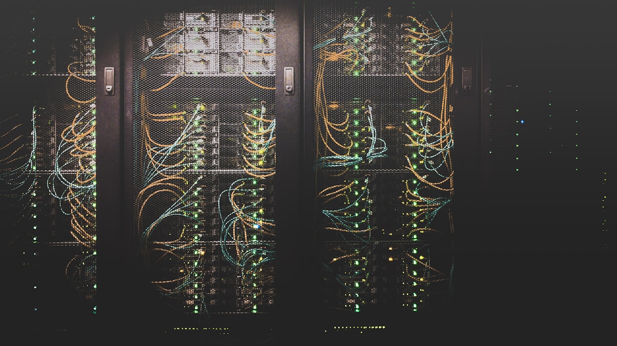
2. Cabling Infrastructure: The Foundation of Wi-Fi 7 Speeds

A common mistake made during network upgrades is mounting a high-speed Wi-Fi 7 Access Point (AP) onto an obsolete cabling system. If you connect a Wi-Fi 7 AP capable of 10 Gbps wireless throughput to an old Cat5e cable, you limit the entire system to a 1 Gbps bottleneck. To extract the true performance of tri-band Wi-Fi 7, your physical infrastructure must match your wireless ambitions.

We must categorise copper cabling standards to determine their suitability for Wi-Fi 7 backhaul installations:

  • Cat5e: Legacy standard. Limited to 1 Gbps at 100 metres. Unsuitable for Wi-Fi 7. It can occasionally run 2.5G Base-T over short distances, but it is highly susceptible to crosstalk and packet loss under load.
  • Cat6: Supports up to 10 Gbps but only up to a maximum distance of 37 to 55 metres depending on the crosstalk environment. For small offices or residential builds in Consett, Cat6 may suffice, but it lacks future-proofing.
  • Cat6a (Recommended Minimum): Fully supports 10 Gbps speeds up to the maximum standard run of 100 metres. It features improved shielding (F/UTP or U/FTP) to eliminate alien crosstalk, making it the ideal baseline for commercial Wi-Fi 7 deployments.
  • Cat7 & Cat8: Cat7 operates at 600 MHz and Cat8 at up to 2000 MHz (supporting 25G/40G Base-T up to 30 metres). While Cat8 is generally reserved for data centres, we occasionally deploy Cat7 or Cat8 shielded copper in highly industrial parts of Consett to shield critical data lines from electromagnetic interference (EMI) generated by heavy machinery.

When installing these complex, multi-node cable runs, clarity is paramount for maintenance and certification. As a matter of professional pride and compliance, I highly recommend adopting a strict identification protocol. You can learn more about this in our comprehensive guide on Best Practices for Labeling Data Cabling Systems. Proper labeling prevents costly troubleshooting hours when managing multi-VLAN Wi-Fi 7 infrastructures.

3. High-Performance Hardware Specifications

To help you select the correct equipment and infrastructure specifications for your Consett project, refer to the technical comparison table below. This outlines the minimum standards required based on the scale of your deployment:

Project Scale Target Speed (Aggregate) Required Cabling PoE Standard IP Rating (Outdoor)
Small Residential / SOHO Up to 3.6 Gbps Cat6 (U/UTP) PoE (802.3af) IP55 (Shed/Garage)
Premium Residential / Estates Up to 9.3 Gbps Cat6a (F/UTP) PoE+ (802.3at) IP66 (Exposed Walls)
Commercial / Hospitality Up to 18.6 Gbps Cat6a (S/FTP) PoE++ (802.3bt Type 3) IP67 (Industrial Yards)
Enterprise / Industrial Up to 46 Gbps Cat7 / Cat8 (S/FTP) PoE++ (802.3bt Type 4) IP67 / IP68 (Corrosive)

4. Power Budgets: Ensuring Stable PoE Delivery

Wi-Fi 7 Access Points pack a massive amount of processing power. Features like 16×16 MU-MIMO, high-frequency radio arrays, and internal cooling fans mean these devices have strict power requirements. If your network switch cannot deliver adequate Power over Ethernet (PoE), your APs will suffer from spontaneous reboots, packet drops, or outright refusal to enable the high-speed 6 GHz radio band.

When calculating your project’s power budget, you must categorise PoE standards:

  • PoE (802.3af): Delivers up to 15.4W at the switch port. Completely inadequate for modern Wi-Fi 7 APs.
  • PoE+ (802.3at): Delivers up to 30W at the port. This is the minimum requirement for entry-level Wi-Fi 7 access points. However, running a high-end AP on PoE+ may force it into a “low power mode,” disabling one of the radio bands or limiting MIMO streams.
  • PoE++ (802.3bt): Delivers up to 60W (Type 3) or 90W (Type 4) of power. This is the gold standard for premium Wi-Fi 7 deployments. High-density APs with 2.5G or 10G uplink ports require 802.3bt power to operate all three bands simultaneously at peak transmit power.

In Consett, where winter temperatures routinely drop below freezing, we must also factor in voltage drop across long outdoor cable runs. Cold temperatures can increase resistance in copper, and if you are using poor-quality Copper Clad Aluminium (CCA) cable instead of pure solid copper (such as British Standard compliant CW1308 or solid Cat6a), your power delivery will fail. Always specify solid-core copper conductors to avoid severe power attenuation.

5. Environmental Weatherproofing: IP66 vs. IP67 for Consett Climates

Consett’s elevated position makes it prone to heavy rainfall, dense mist, and freezing sleet. If your Wi-Fi 7 project involves extending coverage to outdoor spaces—such as pub beer gardens, industrial yards, or perimeter gates—you must pay careful attention to the Ingress Protection (IP) ratings of your enclosures and APs.

Do not compromise on weatherproofing. I recommend two primary standards:

  • IP66 (Dust-tight, protected against powerful water jets): Suitable for sheltered outdoor areas, under eaves, or mounted on walls that are somewhat protected from the worst of the Pennine winds.
  • IP67 (Dust-tight, protected against temporary immersion up to 1 metre): Essential for fully exposed environments. If an AP is mounted on an open pole in an industrial compound, it must be IP67 rated. This ensures that driving wind, heavy rain, and melting ice cannot breach the casing and short-circuit your high-frequency RF components.

GARY PEARCE SECURITY SERVICES Choosing the Right Wi-Fi 7 Tri-Band Speeds for your Project in Consett Core Category: WiFi & Networking

01 / INSTALLATION Standards Spec NSI & SSAIB Compliant Full certification log

02 / HARDWARE Technician Grade Solid Copper Shielding 4K Active Deterrence

03 / COVERAGE Support Area Newcastle & North East Call: 07830 638337

6. Security Compliance: NSI Grade 2/3, SSAIB, and EN 50131 Integration

As an NSI and SSAIB certified installer, I approach network design through a security-first lens. High-speed Wi-Fi 7 is not just for browsing; it is increasingly used as the primary backbone for wireless IP CCTV systems and wireless intruder alarm expanders. If your wireless network is carrying security data, it must comply with European Standards such as EN 50131.

For Grade 2 (medium risk, e.g., standard residential and retail) and Grade 3 (high risk, e.g., commercial warehouses and banks) systems, any wireless path must be resilient, encrypted, and monitored. When integrating IP-based security devices from global market leaders like Hikvision Global Security, the wireless link must be treated as a critical transmission path.

To maintain NSI Grade 2 or 3 compliance across a Wi-Fi 7 network, we implement the following protocols:

  • Network Segregation (VLANs): Security devices, IP cameras, and door controllers must reside on a dedicated, firewalled VLAN completely isolated from guest or staff Wi-Fi networks.
  • WPA3-Enterprise Encryption: Legacy WPA2 is no longer acceptable for high-security environments. Wi-Fi 7 mandates WPA3 for the 6 GHz band, which we extend across all SSIDs using 192-bit cryptographic strength.
  • Supervised Wireless Links: Using the ultra-low latency of Wi-Fi 7, security networks must continuously poll connected nodes. If a jammer or interference compromises the signal for more than a specified number of seconds, an alert must be routed via dual-path signalling to an Alarm Receiving Centre (ARC).

7. Step-by-Step Installation & Commissioning Procedure

Deploying a Wi-Fi 7 network in Consett requires a methodical, professional approach. Below is the exact deployment procedure I use to ensure a flawless installation:

Step 1: The Active RF Site Survey
Before drilling any holes, we conduct an active RF site survey using professional spectral analyzers. This is particularly crucial in Consett’s old stone buildings, where we must measure the exact attenuation rate of 5 GHz and 6 GHz signals passing through thick walls. This survey dictates precise AP placement.

Step 2: Structured Cabling Installation
Run Cat6a or Cat7 shielded solid-core cabling from the central comms cabinet to each AP location. Ensure all cables are terminated with high-quality shielded RJ45 modules or field termination plugs. Ensure all cabling paths avoid high-voltage mains runs to eliminate EMI.

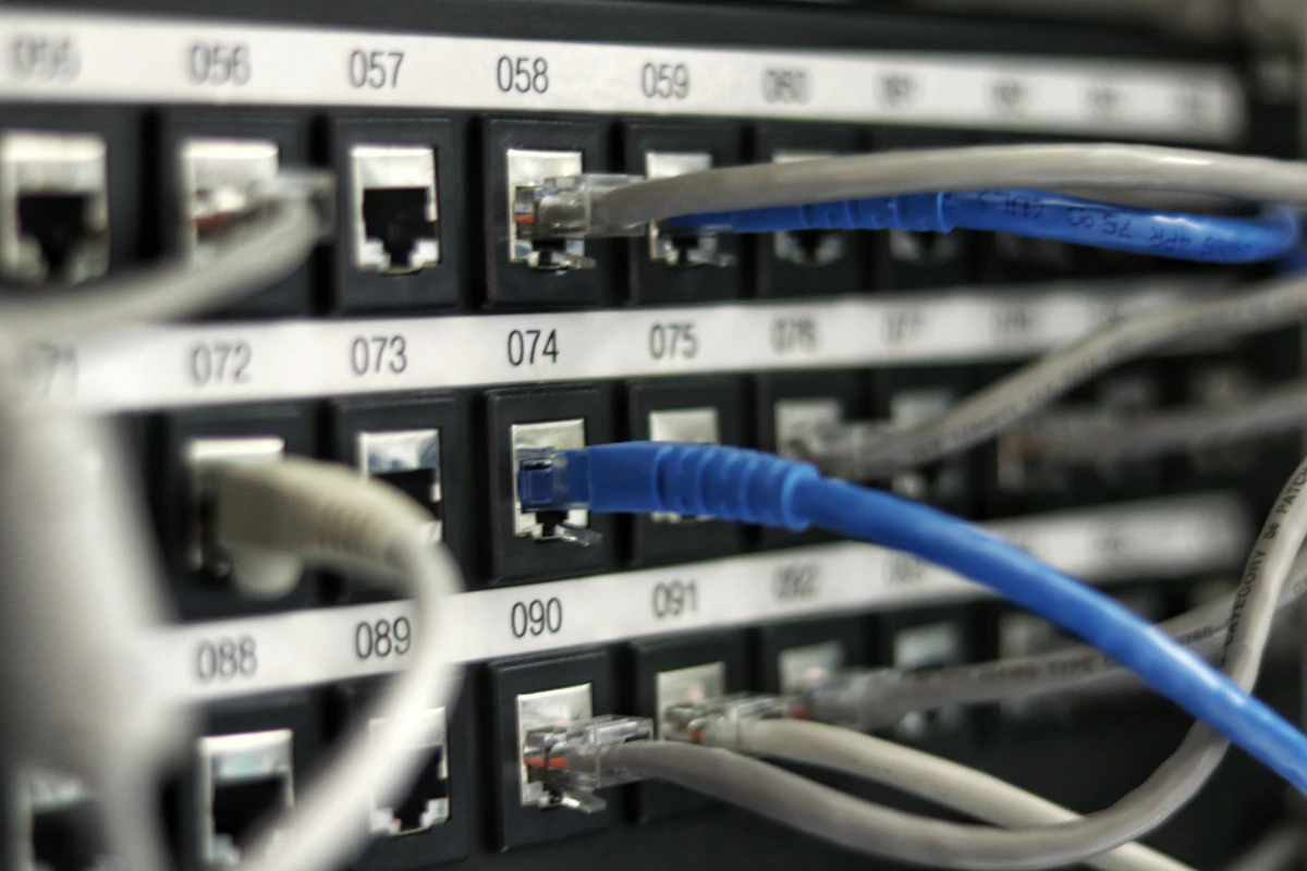
Step 3: Cable Testing and Labeling
Every single copper run must be certified using a calibrated cable analyzer (such as a Fluke DSX-8000). We test for insertion loss, return loss, and NEXT (Near-End Crosstalk). Once certified, we label the cable at both ends using our strict labeling scheme to ensure future maintenance is seamless.

Step 4: Physical Mounting & Powering
Mount the APs securely. For indoor commercial environments, use ceiling tile mounts. For outdoor areas, mount IP67-rated APs using stainless steel brackets to prevent rust from Consett’s damp weather. Connect the APs to a PoE++ managed switch capable of handling the calculated power load.

Step 5: Network Configuration and MLO Tuning
Log into the network controller. Define the separate VLANs for corporate data, guest access, IoT, and IP security. Configure Multi-Link Operation (MLO) to allow compatible Wi-Fi 7 clients to transmit across 5 GHz and 6 GHz bands simultaneously. Set up DFS (Dynamic Frequency Selection) channels correctly to avoid interference from local military or weather radar installations.

Choosing the Right Wi-Fi 7 Tri-Band Speeds for your Project in Consett details

Figure 2: Quality installation standard deployment.

Step 6: Security Compliance Auditing
Test the network against SSAIB and NSI criteria. We simulate a wireless link failure on the security VLAN to verify that the alarm panel flags a fault within the legally required time limit. Verify WPA3 handshake logs and ensure isolation rules are functioning correctly.

8. Troubleshooting Wi-Fi 7 Performance Issues

Even with advanced technology, real-world deployment can present hurdles. Here is how we diagnose and solve the three most common Wi-Fi 7 issues in the North East:

  • Symptom: 6 GHz Band Disappears or Frequently Drops

    Cause: This is almost always a power budget or cable length issue. Wi-Fi 7 APs require massive power to drive the 6 GHz radio. If the switch has negotiated a lower PoE standard (e.g., 802.3at instead of 802.3bt), the AP will disable the 6 GHz band to protect its processor.

    Solution: Check the switch management portal. Ensure the port is delivering full PoE++ (up to 60W). If the cable run is exceptionally long, measure the voltage at the AP end to ensure copper resistance isn’t dropping the power below acceptable limits.

  • Symptom: High Packet Loss and Jitter on Wireless CCTV Streams

    Cause: Severe RF interference or physical attenuation from stone walls, coupled with poorly configured roaming parameters.

    Solution: Enable MLO so the camera streams can dynamically hop between 5 GHz and 6 GHz. If physical barriers are too dense, you must deploy additional APs to achieve line-of-sight propagation, or drop down to a highly directed 5 GHz signal with narrow channel widths (20 MHz or 40 MHz) to increase signal penetration and stability.

  • Symptom: Client Devices Connecting at Low Speeds

    Cause: The client device is defaulting to the 2.4 GHz band because the APs are transmitting at maximum power, making the 2.4 GHz signal look “stronger” than the 5/6 GHz signals.

    Solution: Perform a professional power balance. Reduce the transmit power of the 2.4 GHz radio (e.g., to 12 dBm) while keeping the 5 GHz at 18 dBm and 6 GHz at 20 dBm. This encourages modern client devices to roam onto the higher-speed bands naturally.

Trust the Local NSI/SSAIB Experts

Choosing the right Wi-Fi 7 speeds for your Consett project is not just a matter of reading the box specs. It requires an understanding of structural attenuation, rigorous copper cabling certifications, stable PoE calculations, and strict security compliance. Whether you are upgrading a private estate in Castleside or implementing a multi-site network for an industrial unit on the Number One Industrial Estate, professional design and installation make all the difference.

Do not compromise on your network’s foundation. Ensure your project is future-proofed, compliant, and lightning-fast. For bespoke advice, site surveys, and NSI/SSAIB certified installations across Consett and the wider North East, get in touch with our engineering team today.

Q: What details do you provide regarding Choosing the Right Wireless Access Points for your Project in North Shields?

A: We have written an extensive guide on this. Read our complete guide to Choosing the Right Wireless Access Points for your Project in North Shields or contact Gary Pearce on 07830638337.

Q: What details do you provide regarding Choosing the Right Signal Attenuation for your Project in Newton Aycliffe?

A: We have written an extensive guide on this. Read our complete guide to Choosing the Right Signal Attenuation for your Project in Newton Aycliffe or contact Gary Pearce on 07830638337.

Q: What details do you provide regarding Choosing the Right Ubiquiti UniFi Setup for your Project in Hartlepool?

A: We have written an extensive guide on this. Read our complete guide to Choosing the Right Ubiquiti UniFi Setup for your Project in Hartlepool or contact Gary Pearce on 07830638337.

Q: What details do you provide regarding A Forensic Look at VLAN Segregation Engineering in Hexham?

A: We have written an extensive guide on this. Read our complete guide to A Forensic Look at VLAN Segregation Engineering in Hexham or contact Gary Pearce on 07830638337.

?
Frequently Asked Questions

Q: What details do you provide regarding Choosing the Right Fresnel Zone Clearance for your Project in Berwick-upon-Tweed?

A: We have written an extensive guide on this. Read our complete guide to Choosing the Right Fresnel Zone Clearance for your Project in Berwick-upon-Tweed or contact Gary Pearce on 07830638337.

Need a Professional Quote?

Trust Gary Pearce Home Services for NSI and SSAIB certified installations. Expert, reliable, and compliant.

How to Repair and Maintain Solid Copper vs CCA Cables

How to Repair and Maintain Solid Copper vs CCA Cables

rgba(0,0,0,0.1);” />

An Engineer’s Guide to Solid Copper vs CCA Cables: Repair, Maintenance, and Compliance

In my line of work as an NSI and SSAIB certified Security and Networking Engineer based in Newcastle upon Tyne, I have seen almost every physical layer failure imaginable. From poorly planned containment systems in historic Quayside buildings to suspect, unlabelled bundles stuffed into server racks in modern business parks, the physical layer is where a network succeeds or fails. Among all the issues I diagnose, one recurring hazard stands out: the misuse of Copper Clad Aluminium (CCA) cabling in structured networks, particularly when paired with high-draw Power over Ethernet (PoE) devices or critical security infrastructure.

For any professional installer or network administrator, understanding the structural, electrical, and mechanical differences between pure solid copper and CCA is not just academic—it is a matter of building safety, system reliability, and regulatory compliance. This comprehensive guide details how to identify, repair, maintain, and replace these two cabling mediums, keeping your installations in line with British Standards, NSI Grade 2 or 3 security guidelines, and SSAIB requirements.

Understanding the Technology: Solid Copper vs CCA

To appreciate why Solid Copper and Copper Clad Aluminium perform so differently, we must look at their metallurgy and how high-frequency signals and DC electricity travel through them.

Solid Copper Cabling

Solid copper conductors consist of 100% pure, oxygen-free copper. Pure copper is highly ductile, possesses excellent electrical conductivity (second only to silver), and boasts high tensile strength. In high-performance data cabling standards—ranging from Cat5e and Cat6 up to 10-Gigabit-capable Cat7 and Cat8 systems—solid copper is the benchmark. Because data signals travel near the surface of the conductor due to the “skin effect” at high frequencies (measured in hundreds of Megahertz), and DC power utilizes the entirety of the conductor’s cross-section, solid copper excels at carrying both high-bandwidth data and heavy electrical power simultaneously without excessive attenuation or thermal buildup.

Copper Clad Aluminium (CCA) Cabling

CCA cables are a compromise designed to reduce manufacturing costs. They feature an aluminium core covered with a thin outer sleeve of copper, typically accounting for only 10% to 15% of the conductor’s volume. While high-frequency AC data signals can flow relatively unimpeded along the outer copper skin, low-frequency and DC power signals are forced to travel through the aluminium core. Aluminium has 61% of the conductivity of copper, which means its DC resistance is roughly 55% to 60% higher than a solid copper conductor of the same gauge. This high resistance leads to significant voltage drops over distance and converts wasted electrical energy directly into heat.

Furthermore, aluminium is physically brittle. It suffers from high rate of flex fatigue, meaning it breaks easily when bent, and is highly susceptible to galvanic corrosion when exposed to moisture, as the two dissimilar metals (copper and aluminium) react chemically in a wet environment.

Security & Regulatory Compliance: NSI, SSAIB, and EN 50131

In the UK, installing CCA cable in security and life-safety applications is a major breach of professional standards. When executing a system design under NSI Grade 2 or Grade 3 guidelines, or preparing an installation for an SSAIB audit, the physical integrity of the transmission path is paramount. Under BS EN 50131 (the European standard for Intruder and Hold-up Alarm Systems) and BS 7671 (the IET Wiring Regulations), cabling must be fit for purpose and capable of sustaining operational voltages without excessive drop-offs.

If you are deploying IP CCTV systems, the stability of your infrastructure is critical for compliance with the code of practice set out by the UK Gov Surveillance Commission. This guidance stresses the need for resilient, high-availability video feeds that do not drop frames or experience power-induced dropouts. CCA cables, due to their high DC resistance and tendency to degrade at termination points, fail to meet these stringent reliability standards. Using them in a commercial or public-space security install puts your certification—and your clients’ insurance coverage—at direct risk.

PoE Power Budgets, Heating, and Fire Hazards

The rise of high-power PoE standards has turned the Solid Copper vs CCA debate into a serious fire safety conversation. Let us look at the power envelopes we regularly deploy:

  • PoE (802.3af): Delivers up to 15.4W at the source, operating over two pairs.
  • PoE+ (802.3at): Delivers up to 30.0W at the source, ideal for PTZ cameras and access control readers.
  • PoE++ (802.3bt Type 3 & 4): Delivers up to 60W or 90W respectively, utilizing all four pairs to power active display screens, heavy-duty heaters, and high-performance wireless access points.

When you pass these currents through a cable bundle, the physics of Joule heating ($I^2R$) apply. Because CCA has much higher electrical resistance ($R$), a bundle of CCA cables running PoE+ or PoE++ will experience significant thermal elevation. In enclosed spaces, such as ceiling voids, risers, or containment trunking, this heat build-up can melt the outer PVC sheathing, leading to conductor short-circuits, permanent insulation degradation, and in extreme cases, catastrophic electrical fires. For this reason, British Standards explicitly prohibit the use of non-compliant, non-copper conductors for PoE delivery within structured cabling networks.

Technical Specification Comparison Table

The table below highlights the crucial differences between solid copper and CCA cabling across key technical parameters:

Parameter / Specification Solid Pure Copper Copper Clad Aluminium (CCA)
DC Loop Resistance (per 100m) < 9.38 Ohms > 14.5 Ohms (Up to 60% higher)
Tensile Strength & Ductility High; tolerates pull tension up to 110N. Very low; prone to snapping under minimal tension.
PoE, PoE+, & PoE++ Support Fully certified up to 90W (Type 4) Extremely hazardous; high fire risk.
IDC Termination Performance Excellent gas-tight connection on Krone/110 blocks. Poor; blades slice the copper skin, causing corrosion.
Standards Compliance (TIA/EIA 568) Fully Compliant Non-Compliant
Susceptibility to Oxidation Low; stable over decades. High; rapid degradation when exposed to oxygen.

Testing, Identifying, and Troubleshooting

As a network engineer, you will often inherit systems built by others. You must be able to quickly determine if you are dealing with solid copper or a substandard CCA installation before committing to a maintenance SLA or certifying a network.

GARY PEARCE SECURITY SERVICES How to Repair and Maintain Solid Copper vs CCA Cables Core Category: Data Cabling

01 / INSTALLATION Standards Spec NSI & SSAIB Compliant Full certification log

02 / HARDWARE Technician Grade Solid Copper Shielding 4K Active Deterrence

03 / COVERAGE Support Area Newcastle & North East Call: 07830 638337

On-Site Identification Techniques

  • The Scratch Test: Take a utility knife and gently scrape away the top layer of the conductor’s metallic surface. If the deep orange-brown colour remains, it is pure copper. If a bright, silvery-white metal is exposed beneath, you have caught a CCA cable.
  • The Weight Test: Aluminium is significantly lighter than copper. A standard 305m (1000ft) box of pure copper Cat6 cable weighs approximately 11kg to 14kg. A 305m box of CCA Cat6 will feel noticeably light, weighing in at only 5.5kg to 7kg.
  • The Burn Test: Using a lighter, apply a direct flame to an exposed conductor. A solid copper wire will glow red, heat up, and retain its shape. A CCA wire will quickly degrade, melt, and snap as the aluminium core liquefies at a much lower temperature (660°C compared to copper’s 1085°C).

Field Testing with a Cable Analyser

While visual tests are helpful, the ultimate proof lies in active RF and electrical testing. A basic wiremap tester will not tell you if a cable is CCA; it will only verify pin-to-pin continuity. To expose CCA, you must use a certified level III/IV field tester, such as a Fluke DSX-8000 CableAnalyzer, to perform a full certification suite. Pay close attention to the DC Loop Resistance. If a 60-metre run returns resistance figures expected of a 100-metre run, the cable is almost certainly CCA. High resistance values cause high insertion loss and signal attenuation, which can lead to dropped packets and erratic performance on high-speed data links.

When documenting your tests and mapping out the network topology back to the comms room, keeping clear records is essential. Poor labeling can turn troubleshooting into a nightmare. Be sure to follow our internal guide on the Best Practices for Labeling Data Cabling Systems in Racks to ensure your panels, ports, and cable pathways are systematically mapped for future maintenance runs.

Repair and Maintenance Protocols

When physical damage occurs on a cable run—such as a drill puncturing a drywall cavity, rodent damage, or stress fractures inside conduit—how you resolve the issue depends entirely on the cable material. Below are the practical procedures for handling both scenarios.

Scenario A: Repairing Damaged Solid Copper Cables

Solid copper can be reliably repaired if there is sufficient slack and the damage is localized. However, you should never simply splice individual conductors together with electrical tape. To maintain Category compliance (Cat5e/Cat6) and preserve high-frequency performance, follow these steps:

  1. Isolate the Power: Ensure any PoE sources feeding the run are completely disabled at the switch level.
  2. Assess the Slack: Determine if there is enough physical slack in the run to cut out the damaged section and pull the cable ends back together. If not, you will need to insert a short patch section of identical spec (e.g., solid copper Cat6 to solid copper Cat6).
  3. Use an IDC Junction Box: Cut away the damaged section cleanly. Strip back the outer jacket by no more than 25mm to avoid changing the twist rate of the internal pairs. Use an inline, shielded IDC (Insulation Displacement Connector) junction box designed specifically for Cat6/Cat6A. Punch down the conductors using a high-quality punch-down tool set to low impact, maintaining the twists as close to the terminal as possible.
  4. Re-Test: Run a full autotest on your cable analyser to verify that NEXT (Near-End Crosstalk), return loss, and DC loop resistance are within acceptable limits.

Scenario B: The Reality of CCA Cable “Repairs”

If you encounter damaged CCA cable, do not attempt to repair it. It must be completely extracted and replaced with solid copper.

Why? When you attempt to punch down CCA onto an IDC Krone block, the sharp metal contact blades slice through the thin outer copper layer. Once the aluminium core is exposed to air, oxidation begins immediately. This oxide layer acts as an electrical insulator, rapidly increasing resistance until the connection fails entirely. Additionally, the physical action of pushing a punch-down tool onto brittle aluminium conductors often shears them right at the terminal, leading to a loop of endless frustration. If you try to crimp an RJ45 connector onto CCA, the displacement prongs will struggle to bite cleanly, resulting in poor physical contact that will fail under the slightest strain.

How to Repair and Maintain Solid Copper vs CCA Cables details

Figure 2: Quality installation standard deployment.

From an liability standpoint, repairing a CCA run and leaving it in service for security or active data systems is a major risk. The only professional, SSAIB-compliant option is to pull the compromised run out of the ducting or tray work and pull a fresh, solid copper Cat6 or Cat6a cable in its place.

Weatherproofing Joint Enclosures: Achieving IP66 and IP67

In many of my external Newcastle CCTV installations—whether mounting IP cameras on high-wind seaside structures or routing cables along wet exterior brickwork—weatherproofing is non-negotiable. Water ingress is the number one cause of physical layer failures in outdoor deployments.

If you must join or terminate an outdoor solid copper run (for example, transition from an external gel-filled PE-jacketed cable to an internal LSZH cable), you must use an IP-rated enclosure. Here is how to construct a weatherproof connection:

  • Select the Right Rating: Use an IP66 enclosure if the junction will be subjected to high-pressure water jets, or an IP67 enclosure if there is any risk of temporary submersion.
  • Cable Glands: Pass the cables through compression glands equipped with rubber seals that match the exact outer diameter of your cable jackets. Tighten the dome nuts until the rubber seal visibly deforms around the cable, creating a hermetic seal.
  • Drip Loops: Always shape a physical “drip loop” in the cable run immediately prior to entering the junction box. This ensures gravity pulls running rainwater down and away from the gland entrance rather than channeling it directly into the seal.
  • Self-Amalgamating Tape: For added protection on exposed RJ45 inline couplers, wrap the entire completed joint in high-grade self-amalgamating tape. This tape fuses to itself when stretched, creating a continuous waterproof jacket that locks out moisture.

Never run CCA externally. Because aluminium reacts aggressively with air and water, even the slightest trace of condensation inside a weatherproof enclosure will trigger galvanic corrosion. Within weeks, the copper cladding will flake off, the aluminium core will turn to white dust, and your network connection will drop offline.

Summary for the Field Engineer

Maintaining high standards in security and network infrastructure requires a zero-tolerance policy toward inferior components. When planning or auditing a network, keep these practical points in mind:

  • Verify every drum: Conduct quick scratch and weight checks on any cable delivered to site to confirm it is 100% solid copper before pulling it through walls or conduits.
  • Respect your PoE budgets: Never deliver PoE, PoE+, or PoE++ over CCA. The thermal accumulation in cable bundles poses a genuine fire risk and violates local building regulations.
  • Enforce compliance: Ensure all critical infrastructure links—especially surveillance and alarm networks—are built on certified solid copper to comply with NSI, SSAIB, and EN 50131 standards.
  • Terminate with care: Use quality IDC junctions and structured labeling systems to keep your network organised, highly serviceable, and easy to troubleshoot for years to come.

Q: What details do you provide regarding How to Repair and Maintain PoE Power Budgets?

A: We have written an extensive guide on this. Read our complete guide to How to Repair and Maintain PoE Power Budgets or contact Gary Pearce on 07830638337.

Q: What details do you provide regarding How to Repair and Maintain Keystone Jack Termination?

A: We have written an extensive guide on this. Read our complete guide to How to Repair and Maintain Keystone Jack Termination or contact Gary Pearce on 07830638337.

Q: What details do you provide regarding How to Repair and Maintain Plenum-Rated Cabling (Part 1)?

A: We have written an extensive guide on this. Read our complete guide to How to Repair and Maintain Plenum-Rated Cabling (Part 1) or contact Gary Pearce on 07830638337.

Q: What details do you provide regarding Improving Performance of your PoE Power Budgets?

A: We have written an extensive guide on this. Read our complete guide to Improving Performance of your PoE Power Budgets or contact Gary Pearce on 07830638337.

?
Frequently Asked Questions

Q: What details do you provide regarding How to Repair and Maintain RJ45 Shielded Connectors?

A: We have written an extensive guide on this. Read our complete guide to How to Repair and Maintain RJ45 Shielded Connectors or contact Gary Pearce on 07830638337.

Need a Professional Quote?

Trust Gary Pearce Home Services for NSI and SSAIB certified installations. Expert, reliable, and compliant.

Designing a Custom Junction Box Splicing Network in Wallsend

Designing a Custom Junction Box Splicing Network in Wallsend

rgba(0,0,0,0.1);” />

Designing a Custom Junction Box Splicing Network in Wallsend: A Comprehensive Guide

As a seasoned NSI/SSAIB certified Security and Networking Engineer based right here in Newcastle upon Tyne, I’ve seen my fair share of network challenges across the region, from the bustling city centre to the industrial heartlands of Wallsend. When critical network infrastructure suffers damage – be it due to accidental severing, environmental degradation, or even rodent interference – a complete cable replacement is often neither practical nor economically viable. This is where a meticulously designed and professionally implemented custom junction box splicing network becomes the optimal solution. This guide will walk you through the essential considerations, technical parameters, and best practices for creating a robust, compliant, and long-lasting splicing network, ensuring seamless data and power transmission in even the most demanding Wallsend environments.

Understanding the Need for a Custom Splicing Solution

The decision to splice rather than replace a damaged network cable is typically driven by a combination of factors: cost, time, and logistical complexity. Replacing a lengthy run of buried fibre, an overhead Cat6 cable spanning a large warehouse, or a conduit-encased cable within a heritage building can incur significant expense, disrupt operations for extended periods, and sometimes even be physically impossible without extensive demolition. A custom splicing network, when executed correctly, offers a superior alternative, restoring full network functionality with minimal downtime and maximising the lifespan of existing infrastructure.

However, it’s crucial to understand that splicing is not merely a quick fix. It requires a precise, engineered approach to maintain signal integrity, power delivery capabilities (especially with Power over Ethernet), and environmental resistance. Our goal is to ensure the spliced section is not merely functional, but becomes the most robust and secure part of the entire cable run, exceeding the original installation’s resilience where possible.

Initial Site Assessment and Planning in Wallsend

Every project begins with a thorough site assessment. In Wallsend, this often means contending with unique environmental factors. Proximity to the River Tyne can introduce issues like high humidity, potential for flooding, and increased corrosion risks due to airborne salinity. Former industrial sites may have ground contamination, challenging underground routing, or existing legacy infrastructure to navigate. A detailed assessment typically involves:

  • Damage Extent and Location: Precisely identifying the point(s) of damage, assessing the length of cable to be spliced, and determining if the damage is localised or indicative of a systemic issue.
  • Environmental Analysis: Evaluating exposure to UV radiation, moisture, temperature extremes, chemical agents, and potential mechanical stress. This directly influences the choice of enclosure IP rating and cable type.
  • Existing Cable Specification: Identifying the exact category (Cat5e, Cat6, Cat7, Cat8), shielding (UTP, FTP, STP), and conductor gauge of the damaged cable is paramount to ensure compatibility and performance matching in the splice.
  • Network Requirements: Understanding the current and future bandwidth demands (1Gbps, 10Gbps, 25Gbps, 40Gbps) and whether Power over Ethernet (PoE, PoE+) is being utilised, or is planned, for connected devices such as IP cameras, access control readers, or wireless access points.
  • Security Compliance: For installations integrated into security systems (CCTV, Intruder Alarms), we must adhere to NSI/SSAIB requirements and EN 50131 grading, which dictate specific material and installation standards.

Selecting the Right Components for a Resilient Splicing Network

The success of a splicing network hinges on the quality and appropriate selection of its components. Compromising here can lead to persistent network issues, costly repeat visits, and potential security vulnerabilities.

Junction Box Enclosure: The Heart of the Splice

The enclosure protects the delicate cable terminations from the elements and potential tampering. Its selection is critical for longevity and performance, particularly in external or harsh internal environments.

  • Material: Options typically include UV-stabilised ABS, polycarbonate, or durable metal (e.g., powder-coated aluminium). Polycarbonate offers excellent impact resistance and UV stability, making it ideal for outdoor use. Metal enclosures provide superior electromagnetic shielding and tamper resistance, often preferred for high-security applications.
  • IP Rating (Ingress Protection): This is perhaps the most vital specification for any outdoor or damp location.
    • IP66: “Dust tight” (first 6) and protected against “powerful jets of water” (second 6). This is suitable for most outdoor applications where heavy rain is expected.
    • IP67: “Dust tight” (first 6) and protected against “immersion in water up to 1m for 30 minutes” (second 7). This offers a higher degree of protection, essential for areas prone to temporary submersion or where absolute water ingress prevention is non-negotiable, such as near ground level in Wallsend’s flood-risk zones.

    We always assess the specific environmental exposure to determine if IP66 is sufficient or if the added protection of IP67 is required.

  • Mounting Considerations: Secure mounting is paramount. This includes appropriate fixings for the wall material (brick, concrete, timber), vibration resistance, and ensuring the box is positioned to minimise direct impact or water pooling.
  • Cable Entry Glands: These are crucial for maintaining the enclosure’s IP rating. Compression glands (e.g., M20, M25) provide a secure, watertight seal around the incoming and outgoing cables. The correct size must be selected for the cable diameter, and a rubber gasket or O-ring should always be used to ensure a tight seal against the enclosure wall.

Cabling Standards for Splicing

Maintaining the integrity of the original cable’s category is fundamental. Mixing cable types or using inferior patching often degrades network performance across the entire run.

  • Cat5e (Category 5e): Still prevalent, Cat5e supports Gigabit Ethernet (1000BASE-T) over distances up to 100 metres. It’s suitable for basic data networks and low-power PoE applications. While older, it can still serve its purpose where existing infrastructure dictates its use, but it’s rarely chosen for new installations or demanding splices.
  • Cat6 (Category 6): The current standard for most new commercial installations, Cat6 supports Gigabit Ethernet up to 100 metres and 10 Gigabit Ethernet (10GBASE-T) over shorter distances (typically 37-55 metres, depending on alien crosstalk). Its tighter twists and often thicker conductors make it more robust for PoE and PoE+ applications, offering better heat dissipation.
  • Cat7 and Cat7a (Category 7 and 7a): These categories offer enhanced performance, supporting 10 Gigabit Ethernet over full 100-metre channels and even 25/40 Gigabit Ethernet over shorter links with specific components. They typically feature individual shielding for each twisted pair (S/FTP or F/FTP), providing superior alien crosstalk resistance and reduced electromagnetic interference. While less common for horizontal runs due to their stiffness and the need for GG45 or TERA connectors (not standard RJ45), they are excellent for backbone cabling or specific high-noise environments where future-proofing is critical.
  • Cat8 (Category 8): Designed for 25GBASE-T and 40GBASE-T applications over distances up to 30 metres (Class I) or 20 metres (Class II) using standard RJ45 connectors (Cat8.1) or GG45/TERA (Cat8.2). Cat8 is primarily intended for data centre applications or server-to-switch connections where extreme bandwidth is required. Its use in typical splicing scenarios is rare but might be specified for highly demanding industrial or scientific applications in Wallsend needing ultimate future-proofing over short runs.

When splicing, it is absolutely paramount to match the new cable section to the existing cable’s category and shielding to avoid creating a performance bottleneck. Maintaining the cable’s twist rates as close as possible to the termination point is critical for signal integrity, especially with higher categories.

Ethernet Cable Category Comparison

Category Max Bandwidth Max Distance (1Gbps) Max Distance (10Gbps) Shielding Options PoE Support
Cat5e 1 Gbps 100 metres N/A (Limited) UTP (Unshielded) PoE (802.3af)
Cat6 1 Gbps, 10 Gbps 100 metres 37-55 metres UTP, F/UTP (Foiled) PoE, PoE+ (802.3at)
Cat7/7a 10 Gbps, 25/40 Gbps 100 metres 100 metres S/FTP, F/FTP (Shielded) PoE, PoE+, PoE++
Cat8 25/40 Gbps N/A (Short links only) 30 metres S/FTP, F/FTP (Shielded) PoE, PoE+, PoE++
Note: Max distances for 10Gbps+ are highly dependent on alien crosstalk and channel components.

Connectors and Termination

High-quality termination hardware is non-negotiable. We typically utilise either robust keystone jacks mounted within the enclosure or field-terminable RJ45 plugs.

GARY PEARCE SECURITY SERVICES Designing a Custom Junction Box Splicing Network in Wallsend Core Category: Cable Repairs

01 / INSTALLATION Standards Spec NSI & SSAIB Compliant Full certification log

02 / HARDWARE Technician Grade Solid Copper Shielding 4K Active Deterrence

03 / COVERAGE Support Area Newcastle & North East Call: 07830 638337

  • Keystone Jacks: These modular connectors allow for flexibility and easy testing. They come in both punch-down (IDC) and tool-less designs. For splicing, two keystone jacks (one for the incoming cable, one for the outgoing cable) are mounted onto a small patch panel or directly into the enclosure’s mounting points, then connected via a short patch cable.
  • Field-Terminable Plugs: These allow direct termination of the cable onto an RJ45 plug without needing a wall plate or patch panel. They are more compact but require extremely precise termination to maintain performance, especially for higher categories.
  • Wiring Standards: Adherence to T568A or T568B wiring standards is critical. In the UK, T568B is the most common standard for commercial installations, and consistency across the entire network is essential to avoid wire map errors.
  • Tooling: Professional-grade tooling is a must. This includes precision cable strippers, punch-down tools with impact adjustment, and high-quality crimpers for RJ45 plugs. Using inferior tools significantly increases the risk of poor termination and subsequent network issues.

Power over Ethernet (PoE) Budgets and Considerations

The increasing reliance on PoE-powered devices (PDs) means the splicing network must be designed to handle power delivery effectively. PoE standards define different power levels:

  • PoE (802.3af): Provides up to 15.4W at the port, typically delivering around 12.95W to the PD.
  • PoE+ (802.3at): Offers up to 30W at the port, delivering around 25.5W to the PD.
  • PoE++ (802.3bt Type 3 & Type 4): Type 3 provides up to 60W at the port (51W to PD), while Type 4 delivers up to 90W at the port (71W to PD).

When splicing, we must consider:

  • Cable Gauge: Higher power delivery (PoE+) benefits from thicker conductor gauges (e.g., 23AWG for Cat6/7) to minimise voltage drop and heat generation.
  • Heat Dissipation: Splicing enclosures can become ‘hot spots’ if multiple high-power PoE connections are terminated within a compact space. Proper cable management, ensuring sufficient air circulation (where possible without compromising IP rating), and selecting an enclosure material with good thermal properties are important.
  • Resistance: Each termination point introduces a small amount of resistance. While minimal with professional termination, multiple splices over a long run can accumulate resistance, leading to voltage drop and potential underpowering of PDs. This necessitates precise termination and, where possible, keeping splice points to an absolute minimum.

Installation Procedures and Best Practices

The installation phase is where meticulous planning translates into a reliable network. Our approach prioritises precision, compliance, and future maintainability.

Cable Preparation and Termination

This is arguably the most critical step. Any deviation from best practices here will compromise performance.

  1. Stripping: Carefully remove the outer jacket without nicking the inner conductors. The length of the jacket removed should be just enough to expose the pairs for termination, minimising untwisted lengths.
  2. Untwisting Limits: For Cat5e/6, untwist pairs no more than 1/2 inch (13mm) before termination. For Cat7/8, this limit is even stricter, often 1/4 inch (6mm). Exceeding these limits introduces crosstalk and degrades signal quality.
  3. Maintaining Pair Integrity: Keep the twisted pairs as tight as possible right up to the IDC (Insulation Displacement Connector) or crimp point.
  4. T568B Standard: Consistently terminate all connections using the chosen wiring standard (e.g., T568B: Orange/White, Orange, Green/White, Blue, Blue/White, Green, Brown/White, Brown).
  5. Secure Termination: Ensure each wire is fully seated in the IDC block of the keystone jack or properly crimped into the RJ45 plug. Inspect for any exposed copper, short circuits, or incorrect wire order.

Enclosure Assembly and Weatherproofing

Once terminations are complete, the focus shifts to securing and sealing the splice.

Designing a Custom Junction Box Splicing Network in Wallsend details

Figure 2: Quality installation standard deployment.

  • Cable Routing and Strain Relief: Cables should enter the enclosure via the glands with sufficient slack to allow for re-termination if needed, but not so much as to create a tangled mess. Use cable ties or internal management clips to provide strain relief, ensuring no tension is placed on the terminated conductors.
  • Gland Installation: Install the cable glands securely, ensuring the correct rubber seal is in place and tightened sufficiently to compress it around the cable jacket. Do not overtighten, as this can damage the cable.
  • Internal Protection: For shielded cables (F/UTP, S/FTP), ensure the drain wire or overall shield is properly terminated to the shielded keystone jack or enclosure if grounding is required. This is vital for maintaining electromagnetic compatibility (EMC).
  • Sealant Application: For external installations, a bead of exterior-grade silicone sealant or mastic around the cable glands and mounting points provides an additional layer of weatherproofing.
  • Lid Closure: Ensure the enclosure’s lid gasket is clean and properly seated before securing the lid. Tighten all screws evenly to ensure uniform compression of the gasket across the entire perimeter, maintaining the specified IP rating.

Testing and Certification

No network repair is complete without rigorous testing and, where necessary, certification. This provides assurance of performance and compliance.

  • Continuity and Wire Map Testing: Basic testers confirm that all eight conductors are connected correctly and there are no short circuits or open wires. This is a preliminary check.
  • Performance Certification: For Cat6 and higher, especially with PoE or critical applications, a professional cable certifier (e.g., Fluke Networks Versiv) is essential. This device performs a full suite of tests against TIA/ISO standards, including:
    • Wire Map: Confirms correct wiring.
    • Length: Measures cable segment length.
    • Propagation Delay & Delay Skew: Ensures signals arrive within acceptable timing.
    • Insertion Loss: Measures signal attenuation over the cable.
    • Return Loss: Quantifies reflections on the cable due to impedance mismatches.
    • Near-End Crosstalk (NEXT) & Power Sum NEXT (PS-NEXT): Measures interference between pairs within the cable.
    • Far-End Crosstalk (FEXT) & Power Sum FEXT (PS-FEXT): Measures interference at the far end of the cable.
    • Alien Crosstalk (AXT): Important for 10Gbps+ applications, measures interference from adjacent cables.
    • DC Resistance: Critical for PoE, ensuring minimal power loss.

    A “PASS” result from a certified tester provides documented proof that the spliced segment meets or exceeds the required performance standards, crucial for system warranties and client peace of mind.

Documentation and Labelling

Proper documentation is often overlooked but is fundamental for future maintenance and troubleshooting. Every splice point becomes a critical node in the network and must be clearly identifiable.

  • Internal Guide Reference: For detailed guidance on systematic labelling, I always refer to our internal guide: Best Practices for Labeling Data Cables in a Home Server Room. The principles apply universally, whether it’s a server room or an external junction box.
  • Durable Labels: Use UV-resistant, weatherproof labels with clear, concise numbering/naming conventions. Label both the incoming and outgoing cables, indicating their source and destination or patch panel port.
  • As-Built Diagrams: Create or update existing network diagrams to accurately reflect the location of the junction box, the cable categories involved, and any specific notes about the installation (e.g., IP rating, date of installation, installer name).

Security Compliance and Regulatory Adherence

For systems that form part of a security installation (e.g., CCTV, access control, intruder alarms), adherence to specific standards and certifications is non-negotiable. As an NSI/SSAIB certified engineer, this is at the forefront of my design philosophy.

  • NSI/SSAIB Certification: Both NSI (National Security Inspectorate) and SSAIB (Security Systems and Alarms Inspection Board) are leading certification bodies in the UK. Installations carried out by certified companies like ours must meet rigorous standards, which directly impact cable choice, termination methods, and enclosure security. This ensures the system’s reliability and integrity, crucial for police response and insurance purposes.
  • EN 50131 Grades (for Intruder Alarm Systems): The European standard EN 50131 categorises alarm systems into grades based on the level of protection required:
    • Grade 2: Suitable for low to medium-risk residential and commercial premises. Cabling for Grade 2 systems must offer a reasonable level of resistance to tampering, typically requiring cable integrity monitoring.
    • Grade 3: Designed for medium to high-risk commercial and industrial premises, where a higher degree of protection against sophisticated intruders is needed. For Grade 3 systems, all cabling (including any splices) must be supervised for tampering, cut, or short-circuit. This often dictates the use of screened cables, robust enclosures with tamper switches, and specific termination methods to detect such events. When splicing for Grade 3, the junction box itself must incorporate tamper detection (e.g., lid tamper switch), and the splicing technique must ensure that any attempt to interfere with the splice immediately triggers an alarm.

    The choice of cable (e.g., screened vs. unscreened) and the method of splicing directly influence the ability to meet these grades.

  • Data Protection (GDPR and ICO): While primarily a data network, if the spliced cable carries CCTV footage or access control data that involves personal information, then compliance with data protection regulations, specifically GDPR (General Data Protection Regulation), is essential. This includes securing the physical network infrastructure to prevent unauthorised access to data. The Information Commissioner’s Office (ICO) provides comprehensive guidance on data protection obligations in the UK, and we ensure our physical security designs contribute to overall compliance.

Troubleshooting Common Splicing Network Issues

Even with the most meticulous planning and installation, issues can occasionally arise. Understanding common problems and their remedies is part of a comprehensive service.

  • No Connectivity or Intermittent Connection:
    • Symptom: Device offline, network link light off or flickering.
    • Cause: Most often due to poor termination – a wire not fully seated in the IDC, a bent pin in an RJ45, or an incorrect wire map (e.g., T568A on one side, T568B on the other). Damaged cable glands allowing moisture ingress can also cause intermittent issues as components corrode.
    • Resolution: Re-terminate affected connections, ensuring correct wire order and full seating. Use a wire map tester to confirm correct pin-out. Inspect glands and seals for water ingress.
  • Slow Speeds or Dropped Packets:
    • Symptom: Network operating below expected speed (e.g., 100Mbps instead of 1Gbps), excessive latency, file transfers are slow.
    • Cause: Exceeding untwisting limits during termination, creating excessive crosstalk. Using a cable category inferior to the rest of the run. Physical damage to the cable post-installation. Cable length exceeding specifications. Poor shielding effectiveness if using shielded cables.
    • Resolution: Perform full performance certification with a cable certifier to pinpoint the exact failure (e.g., high NEXT, insertion loss). Re-terminate carefully, maintaining twist rates. Verify cable category matches requirements.
  • PoE Device Failure or Instability:
    • Symptom: PoE-powered device fails to power on, reboots intermittently, or functions erratically.
    • Cause: Insufficient power budget from the PoE switch. Excessive voltage drop across the splice due to high resistance from poor terminations or using a cable with too small a conductor gauge. Heat build-up in the enclosure.
    • Resolution: Verify power budget calculations. Check DC resistance with a certifier. Ensure terminations are robust and clean. Consider using thicker gauge cable for PoE applications. Improve ventilation if safe to do so.
  • Environmental Ingress and Corrosion:
    • Symptom: Water or dust inside the junction box, visible corrosion on connectors, intermittent faults, or complete failure.
    • Cause: Improperly sealed cable glands, damaged enclosure gasket, cracks in the enclosure from UV degradation or impact, incorrect sealant application around mounting points.
    • Resolution: Disconnect power, dry out the enclosure thoroughly. Replace corroded components. Re-seal all entry points and the lid, ensuring the IP rating is fully restored. Consider a higher IP-rated enclosure or better mounting location if the environment is harsher than initially assessed.

Conclusion

Designing and implementing a custom junction box splicing network is a nuanced task that requires a deep understanding of networking principles, environmental factors, and regulatory compliance. Whether addressing an urgent cable repair or proactively reinforcing vulnerable network segments in Wallsend, a professional approach ensures the longevity and performance of your critical infrastructure. By meticulously selecting the correct IP-rated enclosures, matching cabling categories (Cat5e, Cat6, Cat7, Cat8), carefully considering PoE budgets, and adhering to rigorous installation, testing, and documentation standards, we can transform a point of failure into a robust and reliable part of your network. As an NSI/SSAIB certified engineer, my commitment is to deliver solutions that not only restore functionality but also enhance the security, resilience, and future-readiness of your systems, providing peace of mind for years to come.

Q: What details do you provide regarding Designing a Custom Ethernet Cable Splicing Network in Morpeth?

A: We have written an extensive guide on this. Read our complete guide to Designing a Custom Ethernet Cable Splicing Network in Morpeth or contact Gary Pearce on 07830638337.

Q: What details do you provide regarding Designing a Custom Junction Box Splicing Network in Stanley?

A: We have written an extensive guide on this. Read our complete guide to Designing a Custom Junction Box Splicing Network in Stanley or contact Gary Pearce on 07830638337.

Q: What details do you provide regarding Designing a Custom Water Ingress Cable Corruption Network in South Shields?

A: We have written an extensive guide on this. Read our complete guide to Designing a Custom Water Ingress Cable Corruption Network in South Shields or contact Gary Pearce on 07830638337.

Q: What details do you provide regarding Designing a Custom Junction Box Splicing Network in Newcastle?

A: We have written an extensive guide on this. Read our complete guide to Designing a Custom Junction Box Splicing Network in Newcastle or contact Gary Pearce on 07830638337.

?
Frequently Asked Questions

Q: What details do you provide regarding Designing a Custom Water Ingress Cable Corruption Network in Alnwick?

A: We have written an extensive guide on this. Read our complete guide to Designing a Custom Water Ingress Cable Corruption Network in Alnwick or contact Gary Pearce on 07830638337.

Need a Professional Quote?

Trust Gary Pearce Home Services for NSI and SSAIB certified installations. Expert, reliable, and compliant.

Technical Specifications of Automated WAN Failover Backup Hardware

Technical Specifications of Automated WAN Failover Backup Hardware

rgba(0,0,0,0.1);” />

Technical Specifications of Automated WAN Failover Backup Hardware

As an NSI and SSAIB certified Security and Networking Engineer based in Newcastle upon Tyne, I frequently design and commission high-availability networks across the North East of England. In modern IP-centric security systems, an uninterrupted internet connection is no longer a luxury; it is an absolute operational necessity. Whether supporting high-definition IP CCTV arrays streaming to a Remote Monitoring Centre (RMC), managing IP-based access control systems, or handling critical alarm signalling pathways, WAN downtime represents an unacceptable vulnerability.

While primary connections typically rely on high-speed FTTP (Fibre to the Premises) or standard FTTC (Fibre to the Cabinet) lines, physical cabling remains susceptible to local construction accidents, cabinet failures, and vandalism. This is where satellite-based WAN failover—specifically Starlink Broadband—has revolutionised the industry. By utilizing Low Earth Orbit (LEO) satellites, Starlink provides high-throughput, low-latency connectivity that acts as an ideal secondary WAN path. However, integrating Starlink as a resilient, automated failover medium requires strict adherence to technical specifications, precise power budgets, and compliance with stringent British security standards.

1. The Anatomy of Starlink Integration in Failover Networks

To successfully integrate Starlink into an automated WAN failover topology, we must first categorise the hardware configurations across different equipment generations. The physical and logical handoff from the Starlink dish to the local gateway router dictates the overall reliability of the failover mechanism.

Starlink Generation 2 (Actuated) vs. Generation 3 (Standard)

The Starlink Gen 2 system, easily identified by its motorized rectangular dish, utilizes a proprietary, non-standard cable that carries both DC power and data from the Starlink router to the dish. Crucially, the Gen 2 router lacks an integrated RJ45 Ethernet port. For professional installations, we must deploy the proprietary Starlink Ethernet Adapter. This adapter extracts a standard 10/100/1000 Base-T RJ45 port from the proprietary connection, allowing us to patch into our security gateway.

The newer Starlink Gen 3 (Standard/Kickstand) model marks a significant improvement for network engineers. It eliminates the motor in favour of manual alignment via software and features standard, weatherproofed RJ45 Ethernet ports directly on both the dish and the power supply unit. This transitions the installation to a standard structural cabling topology, reducing failure points and eliminating the need for expensive proprietary adapters.

Bypass Mode and Double-NAT Mitigation

Leaving the Starlink router in its default state introduces a “Double-NAT” (Network Address Translation) environment when connected to a secondary enterprise gateway. Double-NAT disrupts VPN tunnels, alters IP header structures, and can prevent secure remote access to CCTV networks. Therefore, enabling Bypass Mode within the Starlink application is an absolute prerequisite. This deactivates the built-in Starlink Wi-Fi and DHCP server, passing the external, dynamic CGNAT (Carrier-Grade NAT) public IP address directly to our security gateway’s secondary WAN port.

2. Structural Cabling Standards & Physical Transmission Limits

In high-interference environments or long-distance outdoor runs, selecting the correct structural cabling standard is vital to preserve data packet integrity and sustain high-wattage power transmission over long periods.

  • Category 5e (Cat5e): Limited to 100 MHz bandwidth. While capable of supporting Gigabit Ethernet up to 100 metres, its thin conductor gauge (typically 24 AWG) makes it highly unsuitable for high-power PoE transmission over long distances due to thermal buildup and voltage drop.
  • Category 6 (Cat6): Operates at up to 250 MHz. Utilizes thicker copper conductors (typically 23 AWG) and a central spline (separator) to reduce Near-End Crosstalk (NEXT). Recommended for standard indoor patch leads and short horizontal runs between the failover gateway and power injectors.
  • Category 6A / Category 7 (Cat6A / Cat7): Operating at 500 MHz and 600 MHz respectively. These standards incorporate individual foil shielding for each twisted pair, surrounded by an overall braided shield (S/FTP). This is highly recommended for running alongside main high-voltage conduits on commercial security sites to prevent Electromagnetic Interference (EMI) from degrading the Starlink WAN link.
  • Category 8 (Cat8): Operates at a massive 2000 MHz but is physically constrained to a maximum distance of 30 metres. This standard is largely restricted to data centre cabinet patching and is rarely practical for outdoor satellite dish deployments.

For Starlink Gen 2 and Gen 3 external runs, we specify pure solid copper (solid core) Cat6 or Cat6A Shielded Twisted Pair (S/FTP) external-grade cable. Copper-Clad Aluminium (CCA) cable must be avoided under all circumstances; CCA exhibits high DC resistance, leading to massive voltage drops that will cause the Starlink dish to drop offline during peak operational power cycles.

Cable Standard Max Bandwidth Conductor Gauge (AWG) Shielding Requirement Ideal Security Deployment Use-Case
Cat5e 100 MHz 24 AWG UTP (Unshielded) Legacy internal patching only; not recommended for outdoor satellite runs.
Cat6 250 MHz 23 AWG UTP or F/UTP Standard indoor network patches and short connection to enterprise firewalls.
Cat6A 500 MHz 23 AWG S/FTP (Individual & Outer Shield) Industry Gold Standard for external Starlink runs up to 100m.
Cat7 600 MHz 22 AWG S/FTP (Individual & Outer Shield) High-EMI environments, industrial estates, or when routed alongside mains cables.
Cat8 2000 MHz 22 AWG S/FTP Shielded Strictly server cabinet to server cabinet linking; distance-capped to 30m.

3. Power Budgets, PoE Standards, and Weatherproofing (IP Ratings)

Deploying automated WAN failover systems in harsh UK environments, such as the wind-swept heights of Northumberland or the damp coastal fringes of Tyneside, demands careful attention to electrical and environmental design.

Power over Ethernet (PoE) Budgets

Starlink dishes are high-power devices. Standard network cameras and IP intercoms operate comfortably on IEEE 802.3af (PoE, up to 15.4W) or IEEE 802.3at (PoE+, up to 30W). Starlink, however, requires significantly more power, particularly when its internal heating element is activated to melt snow or ice.

The Starlink Gen 3 dish requires IEEE 802.3bt Type 4 (PoE++) power, delivering up to 90W to 100W of DC power over all four twisted pairs of the ethernet cable. If utilising a third-party PoE injector to bypass the standard Starlink power supply, the injector must be rated for at least 50-57V DC at 2.0A, specifically configured to output power across pinouts 1,2,4,5 (+) and 3,6,7,8 (-). Standard security switches will shut down ports attempting to draw this level of power unless they are explicitly certified for high-power PoE++ Type 4 operations.

Environmental Weatherproofing: IP66 vs. IP67

All external terminations and hardware connections must be physically protected against dust and moisture ingress. Under the International Protection (IP) marking system, we categorise our enclosures as follows:

GARY PEARCE SECURITY SERVICES Technical Specifications of Automated WAN Failover Backup Hardware Core Category: Starlink Broadband

01 / INSTALLATION Standards Spec NSI & SSAIB Compliant Full certification log

02 / HARDWARE Technician Grade Solid Copper Shielding 4K Active Deterrence

03 / COVERAGE Support Area Newcastle & North East Call: 07830 638337

  • IP66 (Dust-tight, protected against powerful water jets): Suitable for vertically mounted wall enclosures and sheltered outdoor installations. It prevents water ingress from heavy rainfall and high-pressure hose-downs, but does not protect against prolonged immersion.
  • IP67 (Dust-tight, protected against temporary immersion up to 1 metre): Essential for flat-roof installations, ground-level junction boxes, or any location prone to pooling water or standing snow. The Starlink Gen 3 dish connector assembly is factory-rated to IP67 when mated with the official weatherproof cable plug.

When running the cable through external walls, we always enforce the use of a downward drip loop before the cable enters an IP-rated junction box or building envelope. All outdoor RJ45 couplings must be protected by IP67-rated waterproof cable glands featuring internal rubber compression seals to ensure long-term physical reliability.

4. Security Compliance, NSI Grade 2/3, and SSAIB Standards

In the United Kingdom, professional security installations must comply with strict regulatory frameworks. Systems designed to trigger police dispatch must be audited and approved in accordance with standards established by the SSAIB Inspectorate Board and the National Security Inspectorate (NSI).

Dual-Path Signalling & EN 50131 Compliance

Under BS EN 50131-1 and PD 6662 standards, intruder alarms and security monitoring networks are categorised by security grades (Grade 1 to Grade 4). A Grade 3 system—typical for high-value commercial premises, jewellers, and sensitive storage facilities—demands a resilient, dual-path Alarm Transmission System (ATS). This dual-path system requires that if the primary path (e.g., landline FTTP) fails, a secondary, physically independent path (e.g., LEO Satellite or 4G/5G cellular) must immediately take over signalling duties.

By utilizing Starlink as a secondary WAN path, we can easily satisfy the dual-path requirements of ATS Category DP3 or DP4. These standards demand that a path fault on one network must be reported to the Alarm Receiving Centre (ARC) within a few minutes (or seconds, for higher-risk profiles). When Starlink acts as the failover path, its low LEO latency (typically 25ms to 45ms) ensures that heartbeat packets, or polling intervals, maintain compliance without triggering false path-failure alarms at the monitoring station.

Integrating Advanced Deterrents on Failover Networks

A critical consideration during WAN failover scenarios is ensuring that automated smart home actions and active security deterrents remain fully operational. For instance, when an external laser detector or thermal IP camera triggers an intrusion event, the network must quickly process and route automated audio warnings across the site. For premium residential configurations, integrating high-fidelity audio system warnings via IoT integrations is a highly effective automated deterrent. For full operational guidance on this, consult our detailed analysis on Best Practices for Integrating Sonos into Smart Security Triggers.

Maintaining these local and cloud-based smart triggers during a primary fibre outage requires that the local failover gateway routes multicast traffic and local network packets flawlessly across the Starlink backup route, ensuring your active deterrents are never left offline.

Technical Specifications of Automated WAN Failover Backup Hardware details

Figure 2: Quality installation standard deployment.

5. Dual-WAN Failover Gateway Configuration & Logic

The physical presence of a secondary Starlink connection is useless without an enterprise-grade gateway router configured to handle automated failover. The transition must be seamless, rapid, and require zero manual intervention.

Active-Passive vs. Active-Active Failover

In an Active-Passive deployment, the primary WAN (Fibre) handles 100% of the network load. The Starlink interface remains in a warm-standby state. The gateway router continuously monitors the primary WAN connection. If a failure is detected, it instantly shifts the routing table to point all outbound traffic to the Starlink interface.

In an Active-Active configuration, both WAN connections are online simultaneously, and traffic is distributed based on Policy-Based Routing (PBR). For security networks, we typically isolate high-bandwidth, non-critical traffic (such as staff guest Wi-Fi) to the primary connection, while critical telemetry, CCTV streams, and access control databases are duplicated or prioritized across both lines to guarantee continuous uptime.

Configuring WAN Ping Targets and Thresholds

To prevent “flapping”—a highly disruptive state where a degraded primary line rapidly cycles between online and offline—we must configure conservative failover and failback thresholds within our gateway (e.g., Ubiquiti UniFi Dream Machine Pro, MikroTik RouterBOARD, or DrayTek Vigor). The following parameters represent best practice for security-hardened installations:

  • Ping Targets: Do not rely on your ISP’s default gateway IP for connection monitoring, as it may remain responsive even if the wider internet is down. Instead, configure multiple highly available public DNS servers as ping targets (e.g., 1.1.1.1 and 8.8.8.8).
  • Echo Interval: Set the gateway to ping the targets every 3 seconds to ensure rapid detection of packet loss.
  • Failover Threshold: Transition to the Starlink backup WAN if 5 consecutive ping attempts fail (15 seconds total).
  • Failback Threshold: To prevent premature restoration to an unstable primary line, the gateway must require 60 consecutive successful pings (3 minutes of sustained stability) on the primary WAN before switching back.

6. Installation Procedures & Commissioning Checklist

To guarantee that our installations withstand the test of time, our engineering team adheres to a strict physical and logical commissioning checklist during every Starlink WAN failover deployment:

  1. Obstruction Analysis: Prior to mounting the Starlink dish, use the Starlink 3D scanner tool at the exact mounting height. A 100% obstruction-free view of the northern sky is required. Even a minor obstruction (such as a single overhanging branch) will cause brief connection drops that can disrupt UDP-based security streams and VPN connections.
  2. Physical Mounting: Secure the dish using heavy-duty, hot-dip galvanised steel non-penetrating roof mounts (ballasted) or heavy-duty wall brackets. Wind-loading must be calculated to withstand gusts up to 100 mph, common on elevated sites across the UK.
  3. Cabling & Grounding: Run external-grade shielded Cat6A cable from the dish. Bond the STP shielding to the building’s main earthing terminal (MET) using an RJ45 lightning surge protector (e.g., Ubiquiti ETH-SP-G2) before the cable passes through the outer wall. This diverts high-voltage atmospheric static discharges safely to ground.
  4. Bypass Configuration: Power on the Starlink system, connect to the local Wi-Fi, update the dish firmware to the latest stable release, and enable Bypass Mode. Verify that the primary gateway router successfully obtains a public or CGNAT WAN IP address via DHCP.
  5. Simulated Outage Testing: Physically disconnect the primary fibre optic connection at the gateway router. Confirm that the gateway detects the failure and successfully transitions routing tables to the Starlink WAN within 15 seconds. Confirm that remote CCTV streaming and alarm signals continue to reach the ARC without requiring system reboots.

7. Troubleshooting Common Failover Bottlenecks

When diagnosing issues with an existing Starlink failover configuration, engineers should systematically check the following parameters:

Latency-Sensitive VPN Drops: Because Starlink is an LEO satellite network, round-trip times (RTT) will naturally fluctuate between 25ms and 80ms, occasionally spiking higher. If IPSec VPN tunnels drop during these spikes, adjust the VPN gateway’s Keep-Alive and Dead Peer Detection (DPD) parameters. Increasing the DPD delay to 30 seconds and the retry count to 5 will prevent tunnels from collapsing during brief latency spikes.

CGNAT and Port Forwarding Limitations: Starlink utilizes Carrier-Grade NAT (CGNAT), which means your WAN port is assigned a private IP address from the 100.64.0.0/10 range. Standard IPv4 port forwarding will not work over this link. To bypass this limitation for remote CCTV or NVR access, you must transition to IPv6 (fully supported by Starlink), set up a secure, outbound-initiated VPN tunnel (such as WireGuard or OpenVPN), or deploy a cloud-managed SD-WAN solution that bypasses inbound port requirements entirely.

Q: What details do you provide regarding Technical Specifications of Starlink High Performance dish Hardware (Part 3)?

A: We have written an extensive guide on this. Read our complete guide to Technical Specifications of Starlink High Performance dish Hardware (Part 3) or contact Gary Pearce on 07830638337.

Q: What details do you provide regarding Technical Specifications of Automated WAN Failover Backup Hardware (Part 5)?

A: We have written an extensive guide on this. Read our complete guide to Technical Specifications of Automated WAN Failover Backup Hardware (Part 5) or contact Gary Pearce on 07830638337.

Q: What details do you provide regarding Technical Specifications of Low-Earth Orbit Satellite Coverage Hardware (Part 7)?

A: We have written an extensive guide on this. Read our complete guide to Technical Specifications of Low-Earth Orbit Satellite Coverage Hardware (Part 7) or contact Gary Pearce on 07830638337.

Q: What details do you provide regarding Technical Specifications of Automated WAN Failover Backup Hardware (Part 2)?

A: We have written an extensive guide on this. Read our complete guide to Technical Specifications of Automated WAN Failover Backup Hardware (Part 2) or contact Gary Pearce on 07830638337.

?
Frequently Asked Questions

Q: What details do you provide regarding Technical Specifications of Low-Earth Orbit Satellite Coverage Hardware (Part 2)?

A: We have written an extensive guide on this. Read our complete guide to Technical Specifications of Low-Earth Orbit Satellite Coverage Hardware (Part 2) or contact Gary Pearce on 07830638337.

Need a Professional Quote?

Trust Gary Pearce Home Services for NSI and SSAIB certified installations. Expert, reliable, and compliant.

How LED Ambient Backlighting Enhances Security and Efficiency in Gosforth

How LED Ambient Backlighting Enhances Security and Efficiency in Gosforth

rgba(0,0,0,0.1);” />

How LED Ambient Backlighting Enhances Security and Efficiency in Gosforth

In the leafy residential avenues of Gosforth, Newcastle upon Tyne—from the grand Victorian terraces of Elgy Road to the contemporary luxury builds of Gosforth Great Park—homeowners are increasingly investing in bespoke media walls. While these installations are primarily celebrated for their aesthetic impact and high-end audio-visual performance, they hold a hidden, highly technical capability. When designed and engineered to professional standards, the integrated LED ambient backlighting of a media wall ceases to be a mere decorative feature. Instead, it transforms into an active, energy-efficient component of the home’s security and automation ecosystem.

As an NSI and SSAIB certified Security and Networking Engineer, my approach to media wall design prioritises structural integrity, network reliability, and strict compliance with British standards. By bridging the gap between high-performance networking and electronic security, we can program ambient LED backlighting to act as a primary visual alert matrix, an active deterrent against intrusion, and a highly efficient architectural lighting source. This comprehensive guide details the engineering, cabling, power budgets, and compliance pathways required to integrate ambient media wall lighting into a secure, smart Newcastle home.

1. The Technology of Smart Ambient Backlighting and Security Integration

Traditional media wall lighting relies on simple, static LED strips controlled by cheap infra-red remotes. These consumer-grade installations are completely isolated from the rest of the home. In contrast, a professionally engineered system utilizes addressable, low-voltage LED tape (such as 24V COB or digital IC strips like the SK6812 or WS2815) managed by smart lighting controllers that communicate over a local Area Network (LAN) using protocols such as DMX512, Art-Net, KNX, or secure Zigbee/Z-Wave meshes.

By interfacing the lighting controller with the home’s main security control panel (which must comply with EN 50131 standards), the media wall’s backlighting becomes an extension of your home security system. For example, if a perimeter fence sensor or an outdoor IP camera detects an intruder, the media wall’s backlighting can immediately shift from a warm, relaxing amber to a high-intensity, flashing red strobe. This visual cue alerts occupants instantly without the immediate panic of a piercing internal siren, which is particularly beneficial in multi-generational homes or properties with pets.

When designing these systems, we follow the Best Practices for Integrating Security Cameras with Home Automation Hubs to ensure that any motion detected by outdoor IP cameras triggers a localized or media-wall-wide color shift. This creates an immediate, highly visible link between the perimeter of your Gosforth property and your central living space.

Furthermore, this integration allows for advanced “Occupancy Simulation.” When you are dining on Gosforth High Street or away on holiday, the media wall can mimic the natural, dynamic light output of an active television or standard household movement. From the street, this erratic, changing light profile suggests the home is occupied, presenting a far more convincing deterrent to opportunist burglars than a simple static timer plug.

2. Cabling Standards, Power Budgets, and Low-Voltage Engineering

To guarantee that a media wall’s lighting and security integration operates reliably without flickering, signal dropouts, or fire hazards, the underlying infrastructure must be engineered to the highest standards. This requires precise calculations regarding network cabling, power distribution, and voltage drop.

High-Performance Cabling Topologies

Modern smart home systems demand structured cabling. All data runs from the central AV rack or comms closet to the media wall must be specified correctly:

  • Cat5e: The absolute minimum legacy standard, suitable for basic IP control signals but limited in bandwidth and shielding for modern high-data AV distribution.
  • Cat6 (U/UTP or F/UTP): The baseline standard for our Gosforth installations. Supports data rates up to 10 Gbps over shorter runs and provides excellent noise immunity when running alongside lighting power cables.
  • Cat7 / Cat8 (S/FTP): Fully shielded cables featuring individual pair wrapping and an overall braided shield. These are utilized in high-density media walls where LED power drivers, HDMI baluns, and network switches sit in close proximity. This high level of shielding prevents Electromagnetic Interference (EMI) from disrupting sensitive security signals or causing LED flickering.

Power Budgets and PoE Architecture

Managing the electrical load of extensive LED arrays is a critical safety consideration. Traditional 12V LED strips suffer from severe voltage drop over runs exceeding 5 metres, resulting in dimming and colour shifts at the far end of the tape. To mitigate this, we specify 24V DC systems as standard. This doubles the voltage and halves the current (amperage) required for the same wattage output, drastically reducing heat generation and conductor cross-section requirements.

For smart control units, we leverage Power over Ethernet (PoE) technology. Rather than running separate mains power lines to every individual smart bridge or LED controller within the media wall cavity, we utilize central PoE switches:

  • PoE (802.3af): Delivers up to 15.4W of DC power. Ideal for small sensor packages and low-power LED bridge controllers.
  • PoE+ (802.3at): Delivers up to 30W of DC power. Suitable for driving intermediate lighting interfaces, security keypads, and control touchscreens integrated into the media wall facade.
  • PoE++ (802.3bt Type 3/4): Delivers up to 60W or 90W of DC power. This standard can power entire low-voltage LED driver nodes directly over Cat6a cabling, eliminating the need for localized 230V AC mains outlets behind the media wall plasterboard. This significantly reduces the thermal load within the wall cavity.

3. Security Standards, Compliance, and Weatherproofing

Any security integration within a Newcastle home must comply with the strict regulatory frameworks governed by the NSI Security Inspectorate and the SSAIB. When combining architectural lighting with life-safety and security apparatus, maintaining system integrity is paramount.

NSI & SSAIB Compliance (EN 50131)

To maintain an NSI Grade 2 or Grade 3 certification for an insurance-approved intruder alarm system, the auxiliary systems (such as the media wall LED controller) must be physically or logically isolated from the primary alarm transmission paths. We achieve this using opto-isolated relays or secure, one-way IP integration via dry contact modules. This ensures that even if a fault or short-circuit occurs within the decorative LED tape, the main security control panel remains completely unaffected and fully operational.

IP Ratings and Environmental Considerations

While a media wall is an indoor installation, Gosforth properties often feature open-plan designs where the media wall is situated close to bi-fold doors, kitchen areas, or transition zones leading to outdoor patio spaces. In these scenarios, environmental protection must be considered:

  • IP20: Suitable only for fully sealed, dry internal cavities of the media wall where there is zero risk of moisture exposure.
  • IP66 (Dust-tight and protected against powerful water jets): Required if the LED runs extend to high-condensation zones, such as integrated fireplace features or indoor-outdoor transitional borders.
  • IP67 (Dust-tight and protected against temporary immersion): Specified for the lowest base tracks of the media wall or adjacent floor recesses where wet mopping, household spills, or condensation from nearby glazing could compromise the electrical circuitry.

4. Specifications and Integration Options: A Comparative Analysis

To help you understand the architectural choices available for your Gosforth installation, the table below compares the three primary methods we use to drive and control security-linked media wall LED backlighting.

System Specification Option A: 24V Local DC Driver Option B: PoE++ Centralized Drive Option C: DMX512 Bus System
Primary Cable Requirement 3-Core 1.5mm² Twin & Earth + Cat6 Cat6A S/FTP Shielded Solid Copper Cat6 (Data) + 2-Core Low-Voltage Power
Maximum Safe Run Distance 15 Metres (with 2.5mm² feed) 100 Metres (Standard Ethernet Limit) 300 Metres (DMX Bus limitation)
Security System Integration Local Relay / Smart Hub API Direct IP Polling / Managed Switch Hardwired Opto-Isolated I/O Interface
Weatherproofing Potential IP20 to IP67 (Depending on tape) IP66 Maximum (Controller localized) IP67/IP68 External Enclosure options
NSI Grade Compatibility Grade 2 (Via isolated smart hub) Grade 2 (With software partition) Grade 3 (Via certified physical relays)

5. Step-by-Step Installation Procedures for Gosforth Homes

Executing a flawless, safe, and compliant installation within a media wall structure requires a systematic engineering approach. Below is the exact step-by-step procedure our team utilizes on-site in Newcastle.

GARY PEARCE SECURITY SERVICES How LED Ambient Backlighting Enhances Security and Efficiency in Gosforth Core Category: Media Walls

01 / INSTALLATION Standards Spec NSI & SSAIB Compliant Full certification log

02 / HARDWARE Technician Grade Solid Copper Shielding 4K Active Deterrence

03 / COVERAGE Support Area Newcastle & North East Call: 07830 638337

Phase 1: First-Fix Structural Prep and Containment

Before the stud work is closed with plasterboard, we install dedicated containment. This prevents cables from being pinched or damaged during the boarding process. We run 25mm high-impact PVC conduit from the central equipment recess to each lighting zone. This allows for easy cable upgrades or replacements in the future.

Crucially, we maintain a minimum physical separation of 50mm between low-voltage signal cables (Cat6/Cat7) and any 230V AC mains power lines feeding the television, soundbar, or electric fireplace. This eliminates any possibility of induced mains hum or data packet degradation.

Phase 2: LED Mounting Channel Installation

We never apply LED adhesive backing directly to timber or plasterboard. Without proper heat dissipation, high-output LED tape will quickly overheat, leading to premature diode failure and a potential fire hazard. We recess deep-profile anodised aluminium profiles (heatsinks) into the media wall structure. These channels diffuse the light seamlessly, avoiding visible “hotspots,” and act as a thermal sink to keep the LEDs operating at a safe, cool temperature.

Phase 3: Cabling and Termination

Data cabling is terminated using premium shielded RJ45 pass-through connectors or LSA+ punch-down blocks inside a structured patch panel. Low-voltage power lines are crimped and terminated using heat-shrink tubing to ensure airtight, corrosion-resistant connections. All cables are labelled at both ends with printed, weatherproof markers detailing their source, destination, and voltage characteristics.

Phase 4: Controller Configuration and Security Binding

With the physical infrastructure in place, the lighting controller is connected to our dedicated, secure Virtual Local Area Network (VLAN). This network is partitioned specifically for security and home automation traffic, isolated entirely from the guest Wi-Fi or family internet access. We then map the DMX addresses or IP commands within the home automation hub, binding specific lighting scenes to the security system’s output relays.

6. Diagnostic Protocols and Troubleshooting

Even with premium hardware, complex smart home integrations can encounter issues over time. As an SSAIB certified engineer, I employ structured diagnostic routines to quickly locate and resolve faults.

Issue A: LED Flickering or Intermittent Control Response

Root Cause 1: Electromagnetic Interference (EMI) caused by poor cable separation or unshielded data runs.

Diagnostic Action: We utilize a Fluke DSX CableAnalyzer to test the shield continuity and near-end crosstalk (NEXT) of the data lines. If interference is detected, we swap unshielded lines for Cat7 S/FTP cabling and ground the patch panel shield to the main earth terminal.

Root Cause 2: Voltage Drop along the LED strip.

Diagnostic Action: Using a calibrated digital multimeter, we measure the DC voltage at the start of the LED run and compare it to the terminal voltage at the far end. If the drop exceeds 5% of the nominal 24V supply, we install additional power injection lines at the midpoint or far end of the run.

How LED Ambient Backlighting Enhances Security and Efficiency in Gosforth details

Figure 2: Quality installation standard deployment.

Issue B: Integration Latency (Delayed Security Triggering)

Root Cause: Severe network congestion or poor IP routing protocols between the security panel and the lighting controller.

Diagnostic Action: We run a continuous ping test and packet capture (Wireshark) on the security VLAN. If high latency or packet loss is observed, we configure Quality of Service (QoS) rules on the managed switch, prioritizing security broadcast packets (UDP) over standard multicast media streams.

Issue C: False Security Triggers from the Ambient Light

Root Cause: High-intensity dynamic lighting from the media wall spilling onto nearby indoor PIR (Passive Infra-Red) motion sensors, confusing their thermal detection elements.

Diagnostic Action: We readjust the physical positioning of the PIR sensors to eliminate direct line-of-sight with the media wall or upgrade traditional thermal-only PIRs to modern Dual-Technology sensors (PIR + Microwave), which are immune to rapid ambient light changes.

7. Maximising Electrical and Operational Efficiency

A major advantage of integrating LED ambient lighting into your Gosforth home is the substantial gain in operational efficiency. Traditional architectural lighting relied on halogen or standard LED bulbs scattered across a ceiling, which often consumed significant energy and created localized heat build-up. Modern 24V COB LED tapes draw a fraction of the power while delivering a much higher lumen-per-watt ratio.

By automating these lights through the home security system, they only operate when strictly necessary. For instance, when the alarm system is set to “Night Mode,” the home automation system automatically dims the media wall to a 1% warm hue, acting as an ultra-low-energy nightlight for hallways or open-plan areas. If the house is armed in “Away Mode,” all ambient lighting is completely shut down, eliminating phantom power draw from idling controllers.

Additionally, because these lighting profiles can be programmed to run in sync with the natural astronomical clock of Newcastle upon Tyne, they shift dynamically from cool energizing light during the overcast winter afternoons to warm, biological-friendly tones as night falls. This supports your circadian rhythm while ensuring your home’s energy footprint remains exceptionally low.

Conclusion: The Smart Home Standard in Newcastle

For discerning homeowners in Gosforth and the wider Tyne and Wear region, a media wall represents a significant investment in comfort, entertainment, and property value. However, viewing a media wall solely through the lens of interior design is a missed opportunity. By employing advanced low-voltage engineering, strict compliance with NSI and SSAIB principles, and high-performance structured cabling, we transform these architectural features into powerful, efficient, and reliable security assets.

Whether it is through the deterrent power of realistic occupancy simulation, the instant clarity of visual alarm alerts, or the sleek integration of energy-saving automation, ambient LED backlighting bridges the gap between luxury living and robust home protection. When you are ready to design, install, or upgrade your home security and media systems, always insist on certified professionals who understand the intricate relationship between physical cabling, network security, and compliance standards.

Q: What details do you provide regarding How AV Receiver Power Distribution Enhances Security and Efficiency in Blyth?

A: We have written an extensive guide on this. Read our complete guide to How AV Receiver Power Distribution Enhances Security and Efficiency in Blyth or contact Gary Pearce on 07830638337.

Q: What details do you provide regarding How Ventilation for AV Equipment Enhances Security and Efficiency in Houghton-le-Spring?

A: We have written an extensive guide on this. Read our complete guide to How Ventilation for AV Equipment Enhances Security and Efficiency in Houghton-le-Spring or contact Gary Pearce on 07830638337.

Q: What details do you provide regarding How Plasterboard Boarding and Skimming Enhances Security and Efficiency in Middlesbrough?

A: We have written an extensive guide on this. Read our complete guide to How Plasterboard Boarding and Skimming Enhances Security and Efficiency in Middlesbrough or contact Gary Pearce on 07830638337.

Q: What details do you provide regarding How Subwoofer Acoustic Isolation Enhances Security and Efficiency in Amble?

A: We have written an extensive guide on this. Read our complete guide to How Subwoofer Acoustic Isolation Enhances Security and Efficiency in Amble or contact Gary Pearce on 07830638337.

?
Frequently Asked Questions

Q: What details do you provide regarding How Hidden Cable Access Hatches Enhances Security and Efficiency in Prudhoe?

A: We have written an extensive guide on this. Read our complete guide to How Hidden Cable Access Hatches Enhances Security and Efficiency in Prudhoe or contact Gary Pearce on 07830638337.

Need a Professional Quote?

Trust Gary Pearce Home Services for NSI and SSAIB certified installations. Expert, reliable, and compliant.

Comparing Heavy Duty Steel TV Brackets Options for Modern Homes

Comparing Heavy Duty Steel TV Brackets Options for Modern Homes

rgba(0,0,0,0.1);” />

Comparing Heavy Duty Steel TV Brackets Options for Modern Homes

In today’s modern homes, the installation of heavy duty steel TV brackets has become increasingly popular due to their durability and strength. These brackets offer a secure solution for mounting large, high-definition televisions on walls while ensuring they remain safely anchored in place. This comprehensive guide will explore the various options available, focusing on technical parameters such as cabling standards, power budgets, weatherproofing, and security compliance.

Technical Parameters

  • Cabling Standards: When choosing a heavy duty steel TV bracket, it’s essential to consider the cabling standard that best suits your home’s wiring infrastructure. Cat5e, Cat6, Cat7, and Cat8 cables are available options, each offering different bandwidth capabilities and speeds.
  • Power Budgets: Power over Ethernet (PoE) and PoE+ are two popular power budget methods used in modern homes. These technologies allow the TV bracket to receive both data and power through a single Ethernet cable, simplifying installation and reducing clutter.
  • Weatherproofing: For outdoor installations or areas prone to moisture, it’s crucial to select a bracket with an appropriate IP rating (e.g., IP66 or IP67) to ensure protection against water and dust ingress.
  • Security Compliance: Ensuring the TV bracket meets relevant security standards such as NSI Grade 2/3, SSAIB, or EN 50131 is essential for maintaining the safety and integrity of your home’s AV system.

Sections Explaining Technology, Installation Procedures, and Troubleshooting

  1. Technology:

    Understanding the technical aspects of heavy duty steel TV brackets is crucial for selecting the most suitable option for your home. This section will delve into the advanced features such as cabling standards (Cat5e, Cat6, Cat7, Cat8), power budgets (PoE, PoE+), weatherproofing (IP66, IP67), and security compliance (NSI Grade 2/3, SSAIB, EN 50131).

    Ubiquiti UniFi Networks offers a comprehensive range of products designed to meet these standards, ensuring reliable performance and compatibility with modern home AV systems.

  2. Installation Procedures:

    This section will guide you through the installation process of heavy duty steel TV brackets, from selecting the appropriate mounting location to securing the bracket to the wall. It will also cover connecting cables and setting up power supply options such as PoE or PoE+.

    GARY PEARCE SECURITY SERVICES Comparing Heavy Duty Steel TV Brackets Options for Modern Homes Core Category: TV Wall Mounting

    01 / INSTALLATION Standards Spec NSI & SSAIB Compliant Full certification log

    02 / HARDWARE Technician Grade Solid Copper Shielding 4K Active Deterrence

    03 / COVERAGE Support Area Newcastle & North East Call: 07830 638337

    • Choose a suitable wall location for your television that provides optimal viewing angles and minimizes glare.
    • Mark the spot where you want to mount the bracket using a level to ensure it’s straight.
    • Follow the manufacturer’s instructions for attaching the heavy duty steel TV bracket to the wall, ensuring it is securely fastened.
    • Carefully connect all cables, including power and data connections as required by your chosen cabling standard (Cat5e, Cat6, Cat7, or Cat8).
  3. Troubleshooting:

    Even with proper installation, issues may arise. This section will address common problems and their solutions, such as signal loss, connectivity issues, or instability in the TV’s mounting.

    • If you experience signal loss, check all connections for loose cables or damaged connectors. Ensure that your cabling standard (Cat5e, Cat6, Cat7, or Cat8) is appropriate for your home’s wiring infrastructure and AV equipment requirements.
    • Connectivity issues can often be resolved by restarting both the TV and any associated devices. If problems persist, verify that all cables are securely connected and check for interference from other electronic devices in the area.
    • In case of instability in the TV’s mounting, first ensure that the heavy duty steel bracket is correctly installed according to manufacturer guidelines. Check that all screws and bolts are tightened securely, and if necessary, consult a professional installer for further assistance.

Comparison Table

Feature Option 1 Option 2 Option 3
Cabling Standard Cat5e Cat6 Cat7
Power Budget (PoE/PoE+) Yes No Yes
Weatherproofing (IP66/IP67) No Yes No
Security Compliance (NSI Grade 2/3, SSAIB, EN 50131) No Yes No

In conclusion, selecting the right heavy duty steel TV bracket for your modern home requires careful consideration of various technical parameters and features. By understanding cabling standards, power budgets, weatherproofing requirements, and security compliance standards, you can ensure that your television mounting solution is reliable, efficient, and safe.

Comparing Heavy Duty Steel TV Brackets Options for Modern Homes details

Figure 2: Quality installation standard deployment.

For more information on integrating AV cabling into new build construction, refer to our internal guide: Best Practices for Integrating AV Cabling into New Build Construction.

Q: What details do you provide regarding Comparing VESA Mounting Standards Options for Modern Homes (Part 1)?

A: We have written an extensive guide on this. Read our complete guide to Comparing VESA Mounting Standards Options for Modern Homes (Part 1) or contact Gary Pearce on 07830638337.

Q: What details do you provide regarding Comparing HDMI Cavity Routing Options for Modern Homes (Part 2)?

A: We have written an extensive guide on this. Read our complete guide to Comparing HDMI Cavity Routing Options for Modern Homes (Part 2) or contact Gary Pearce on 07830638337.

Q: What details do you provide regarding Comparing TV Mounting Safety Standards Options for Modern Homes (Part 3)?

A: We have written an extensive guide on this. Read our complete guide to Comparing TV Mounting Safety Standards Options for Modern Homes (Part 3) or contact Gary Pearce on 07830638337.

Q: What details do you provide regarding Comparing TV Mounting Safety Standards Options for Modern Homes (Part 1)?

A: We have written an extensive guide on this. Read our complete guide to Comparing TV Mounting Safety Standards Options for Modern Homes (Part 1) or contact Gary Pearce on 07830638337.

?
Frequently Asked Questions

Q: What details do you provide regarding Comparing Articulating Cantilever Brackets Options for Modern Homes?

A: We have written an extensive guide on this. Read our complete guide to Comparing Articulating Cantilever Brackets Options for Modern Homes or contact Gary Pearce on 07830638337.

Need a Professional Quote?

Trust Gary Pearce Home Services for NSI and SSAIB certified installations. Expert, reliable, and compliant.

Common Mistakes to Avoid in Coaxial Cable Attenuation setups in Jarrow

Common Mistakes to Avoid in Coaxial Cable Attenuation setups in Jarrow

rgba(0,0,0,0.1);” />

Optimising RF Distribution in South Tyneside: Engineering Precision with Gary Pearce

As an NSI and SSAIB certified Security and Networking Engineer based here in Newcastle upon Tyne, I have spent decades climbing ladders, scanning RF spectrums, and diagnosing signal degradation across Tyne and Wear. One of the most common, yet misunderstood, issues I encounter when visiting properties in Jarrow is incorrect signal levels in coaxial distribution networks. Whether it is a residential property experiencing pixelation on Freeview or a commercial multi-dwelling unit (MDU) distributed system suffering from intermodulation distortion, the culprit is often a misunderstanding of coaxial cable attenuation.

Jarrow’s geographical location presents unique RF challenges. Positioned along the River Tyne, installations must contend with signal reflections from the water, interference from industrial zones, and varying signal paths from the Pontop Pike transmitter or the local Chatton relay. To overcome these issues, many installers reflexively fit high-gain masthead amplifiers, only to overwhelm the tuner of the television or set-top box. Conversely, over-attenuating the signal degrades the Carrier-to-Noise Ratio (CNR), plunging the digital multiplexes (MUXes) below the cliff-edge threshold of digital television reception. This guide will walk you through the critical mistakes to avoid, the engineering principles of attenuation, and how to design a balanced, resilient RF distribution system.

1. Understanding Coaxial Attenuation: The Physics of RF Loss

Before we look at the physical mistakes, we must understand the mathematics of RF signal propagation. Attenuation is the loss of signal strength as it travels through a medium, measured in decibels (dB) per unit length (typically per 100 metres). In coaxial cable, attenuation is not uniform across all frequencies. Because of a phenomenon known as the “skin effect” and dielectric losses, higher frequencies attenuate at a much faster rate than lower frequencies. This frequency-dependent attenuation is known as tilt or slope.

In a standard Jarrow installation, we primarily deal with the UHF band (typically 470 MHz to 694 MHz following the 700 MHz clearance for 5G mobile networks). If you run a 50-metre length of low-quality coax from a loft space down to a basement media hub, the signal at the higher frequency MUXes will be significantly weaker than the lower frequency ones. This unequal attenuation must be balanced. Common mistakes include:

  • Assuming All Attenuators Are Equal: Installers often use cheap resistive attenuators that introduce impedance mismatches, leading to standing waves and high Voltage Standing Wave Ratio (VSWR).
  • Neglecting the Slope: Fitting a flat-line attenuator when the system requires a slope-compensating attenuator (tilt equaliser) to reduce the signal at lower frequencies while leaving higher frequencies untouched.
  • Targeting the Wrong Signal Window: The ideal signal level at a TV tuner outlet is between 45 dBµV and 70 dBµV (decibel microvolts) according to UK DTG (Digital TV Group) guidelines. Any signal exceeding 80 dBµV will overdrive the tuner’s front-end, causing digital clipping and harmonic distortion that mimics a weak signal.

2. Integrating Modern Hybrid Networks: Coax, Cat6, and Security Compliance

In modern smart home installations across Jarrow, TV aerial systems no longer exist in isolation. They are frequently integrated with structured cabling networks and security frameworks. When deploying these complex systems, we must carefully categorise our cabling standards and understand how RF distribution interacts with Ethernet infrastructure, such as Cat5e, Cat6, Cat7, and Cat8 copper lines.

For instance, modern IP-based security cameras and video baluns are increasingly replacing traditional analogue coax CCTV runs. When installing premium security integrations, as detailed in our comprehensive guide on the Best Home Security Cameras UK 2026: Features, Brands & Buying Guide, we must ensure that high-frequency RF signals do not leak into adjacent twisted-pair networking lines, and vice versa. High-speed data on a Cat6a or Cat8 cable can generate electromagnetic interference (EMI) if the coaxial cable run alongside it lacks adequate shielding (Class A or Class A+ double/quad shielded coax, such as WF100 or copper-on-copper equivalents).

Furthermore, when deploying smart security hubs that consolidate TV, data, and security controls, adherence to strict industry compliance standards is mandatory. If you are integrating an RF modulator to broadcast your CCTV feed to every television in a Jarrow home, the entire hardware enclosure and power delivery system must align with SSAIB and NSI Grade 2 or Grade 3 security protocols under EN 50131 standards. This is particularly crucial if the coaxial run crosses paths with security-critical infrastructure, such as external IP cameras powered via high-voltage Power over Ethernet (PoE/PoE+) networks.

3. Environmental Factors & Mechanical Integrity in South Tyneside

The maritime and industrial climate of Jarrow, situated near the North Sea coast and the River Tyne, introduces environmental challenges that directly impact signal attenuation over time. Saltwater moisture, wind loading, and industrial pollutants cause rapid oxidation of copper and aluminium components. To prevent mechanical and chemical degradation of your RF and network setups, adhere to the following strict parameters:

Ingress Protection (IP) Ratings

Any connection made outdoors—whether at the antenna masthead, an external splitter, or an inline attenuator—must be housed in a weatherproof enclosure rated to at least IP66, though IP67 is highly recommended for exposed coastal areas. An IP66 enclosure protects against powerful water jets, while IP67 allows for temporary immersion, guaranteeing that driving rain on a stormy Tyneside night will not seep into your F-connectors.

Galvanic Corrosion & Moisture Ingress

When moisture enters a coaxial cable, it travels down the braid via capillary action (water capillary draw). This oxidises the copper braid, altering its physical properties and dramatically increasing the cable’s attenuation rate. This is known as “wet cable syndrome”. Once a cable is wet, it acts as a low-pass filter, rendering high-frequency Freeview channels completely unreceivable. Always use gel-filled or flooded coaxial cables for external runs, and use compression F-connectors rather than cheap screw-on types to create an airtight seal.

4. Cable Standards & Media Infrastructure Comparison

To design an efficient system, we must select the correct cable for the correct application. Below is a detailed technical comparison of the media and networking cables we commonly install and balance in residential and commercial settings across Jarrow:

Cable Type Bandwidth / Frequency Attenuation Rate (Per 100m) Primary Jarrow Application Weatherproofing / Jacket
RG6 (WF100 Class A) Up to 3000 MHz (UHF/SAT) ~15.0 dB @ 800 MHz Standard TV Aerial & Satellite Runs LSZH (Internal) / PE (External)
RG11 (Heavy Duty) Up to 3000 MHz (UHF/SAT) ~9.5 dB @ 800 MHz Long Backbone Trunk Runs / MDUs PE Waterproof Flooded (IP67 Class)
Cat6 / Cat6a 250 MHz / 500 MHz N/A (Digital IP Packets) IP CCTV (PoE) & HDBaseT Video LSZH (NSI/SSAIB Compliant)
Cat8 2000 MHz N/A (Digital IP Packets) High-Speed Backbone / Server Rooms Fully Shielded S/FTP Only

5. Step-by-Step Installation & Attenuation Balancing Procedure

To avoid the classic mistake of “blind attenuation”—where an installer simply plugs in a 10 dB attenuator and hopes for the best—you must follow a systematic, step-by-step engineering procedure using professional tools (such as a Promax or Televes spectrum analyser).

Step 1: Measure the Raw Signal at the Masthead

Before connecting any amplifiers or distribution equipment, connect your field strength meter directly to the downlead of the aerial. Ensure the aerial is correctly aligned to Pontop Pike (bearing approximately 201 degrees from Jarrow, depending on your exact line of sight). Note the power level of the weakest and strongest digital MUXes. Also, measure the Modulation Error Ratio (MER)—it should be greater than 28 dB for a stable digital signal.

Step 2: Calculate Your Total System Loss

Do not wait until the system is built to find out your signal is too weak. Calculate the mathematical losses of your cable runs and passive splitters:

GARY PEARCE SECURITY SERVICES Common Mistakes to Avoid in Coaxial Cable Attenuation setups in Jarrow Core Category: TV Aerials

01 / INSTALLATION Standards Spec NSI & SSAIB Compliant Full certification log

02 / HARDWARE Technician Grade Solid Copper Shielding 4K Active Deterrence

03 / COVERAGE Support Area Newcastle & North East Call: 07830 638337

  • WF100 Coaxial Loss: Allow roughly 1.5 dB loss per 10-metre run at UHF frequencies.
  • 2-Way Splitter Loss: Typically introduces 3.5 dB to 4.0 dB of passive attenuation.
  • 4-Way Splitter Loss: Typically introduces 7.5 dB to 8.0 dB of passive attenuation.
  • Wall Outlet Loss: Standard isolated plates introduce 0.5 dB to 1.5 dB of loss.

Step 3: Correcting Signal Saturation (Over-Amplification)

If your raw signal at the loft space is 75 dBµV and you run it through a 20 dB gain launch amplifier, your output is 95 dBµV. This will overwhelm any modern digital TV tuner. If you see pixelation and your meter reads >80 dBµV, you must introduce a coaxial attenuator.

Insert a high-quality, screened, metal-bodied F-connector attenuator (for example, a 6 dB or 12 dB fixed attenuator) at the input of the amplifier or immediately before the TV tuner, rather than at the aerial itself. Attenuating at the input of the amplifier prevents the amplifier itself from clipping and generating internal harmonic distortion.

Step 4: Implementing Tilt Equalisation

If your long-run cable drops the high-frequency MUXes (e.g., UHF Channel 45) to 48 dBµV, but the low-frequency MUXes (e.g., UHF Channel 21) remain at 68 dBµV, a flat attenuator is useless. You must install a slope or tilt attenuator. Adjust the slope dial until the signal levels across the entire frequency spectrum are flattened to within 3 dB of each other. This ensures consistent decoding across all Freeview channels.

Step 5: Inspecting Security & Network Separation

If you are routing coaxial cables alongside PoE+ IP cameras or network nodes supplied by enterprise hardware manufacturers, such as Hikvision Global Security, ensure that all coaxial shields are grounded to the building’s main earth terminal (MET). This prevents ground loops and ensures that transient high-voltage surges on network switches do not travel back along the coaxial copper sheath into your television tuners.

6. Troubleshooting Guide: Diagnosing Common Attenuation Errors

When an RF system in Jarrow fails, it is critical to diagnose the root cause systematically. Here is how to distinguish between too much attenuation (weak signal) and too little attenuation (overdriven signal/intermodulation):

Symptom A: Pixelation on Selected Channels (High-Frequency MUXes Only)

If you are missing channels like Film4 or ITV3 but can perfectly receive BBC One, your issue is high-frequency slope attenuation. The cable run is likely too long, poor quality, or water-damaged.

The Fix: Replace the cable with CAI-certified Class A WF100 coax, or install an active tilt-pre-emphasis amplifier that boosts higher frequencies more than lower frequencies.

Symptom B: All Channels Pixelating, Signal Strength Reads “100%”

This is a classic symptom of receiver overload. The television’s automatic gain control (AGC) is saturated, causing massive digital bit errors (high Pre-RS BER).

The Fix: Connect an in-line variable attenuator (0-20 dB) directly to the TV’s aerial input. Turn the dial clockwise until the signal level drops to approximately 60 dBµV and the picture stabilises.

Symptom C: High Bit Error Rate (BER) Despite Good Signal Strength

If your meter reads 62 dBµV (perfect amplitude) but the MER is below 22 dB, your signal is contaminated by noise or interference. This is often caused by LTE/5G phone mast signals leaking into unshielded coaxial connections or poor quality, non-attenuated amplifiers boosting background RF noise.

The Fix: Install a high-rejection 5G/LTE filter (cutting off sharply above 694 MHz) directly before your distribution amplifier. Ensure all F-connectors are high-quality compression types and discard any old, plastic-bodied coax splitters.

Common Mistakes to Avoid in Coaxial Cable Attenuation setups in Jarrow details

Figure 2: Quality installation standard deployment.

7. Gary Pearce’s Expert Installation Checklist

To ensure your Jarrow installation complies with modern engineering standards, runs reliably for decades, and interfaces cleanly with security and networking systems, check off every item on this professional list:

  • ✓ Cable Class: Use only CAI (Confederation of Aerial Industries) benchmarked Class A double-shielded coaxial cable (e.g., Webro WF100). Never use thin, single-shielded brown or white RG59 cable.

  • ✓ Weatherproofing: All external terminations must use gel-filled F-compression connectors and be protected by IP66/IP67 self-amalgamating tape or weatherboots inside a UV-stabilised housing.

  • ✓ Attenuation Positioning: Always place fixed attenuators at the input side of distribution equipment rather than the output, keeping internal noise figures (NF) as low as possible.

  • ✓ Security & Network Compliance: Ensure all integrated RF structures alongside smart home systems adhere strictly to NSI/SSAIB guidelines, utilising LSZH (Low Smoke Zero Halogen) cabling internally.

By avoiding these common coaxial attenuation mistakes, you will ensure a crystal-clear television signal and a robust, future-proofed home entertainment network that integrates seamlessly with your property’s security systems. If you need any assistance engineering a high-performance network or security setup in Jarrow, Gateshead, or Newcastle, remember that precision, testing, and compliance always yield the best results.

Q: What details do you provide regarding Common Mistakes to Avoid in Coaxial Cable Attenuation setups in Stockton-on-Tees?

A: We have written an extensive guide on this. Read our complete guide to Common Mistakes to Avoid in Coaxial Cable Attenuation setups in Stockton-on-Tees or contact Gary Pearce on 07830638337.

Q: What details do you provide regarding Common Mistakes to Avoid in DAB Radio Aerials setups in Peterlee?

A: We have written an extensive guide on this. Read our complete guide to Common Mistakes to Avoid in DAB Radio Aerials setups in Peterlee or contact Gary Pearce on 07830638337.

Q: What details do you provide regarding Common Mistakes to Avoid in Coaxial Cable Attenuation setups in Sunderland?

A: We have written an extensive guide on this. Read our complete guide to Common Mistakes to Avoid in Coaxial Cable Attenuation setups in Sunderland or contact Gary Pearce on 07830638337.

Q: What details do you provide regarding Common Mistakes to Avoid in Coaxial Cable Attenuation setups in Ponteland?

A: We have written an extensive guide on this. Read our complete guide to Common Mistakes to Avoid in Coaxial Cable Attenuation setups in Ponteland or contact Gary Pearce on 07830638337.

?
Frequently Asked Questions

Q: What details do you provide regarding Common Mistakes to Avoid in DAB Radio Aerials setups in Spennymoor?

A: We have written an extensive guide on this. Read our complete guide to Common Mistakes to Avoid in DAB Radio Aerials setups in Spennymoor or contact Gary Pearce on 07830638337.

Need a Professional Quote?

Trust Gary Pearce Home Services for NSI and SSAIB certified installations. Expert, reliable, and compliant.

Why Professional Vandal-Proof IK10 Enclosures Matters for Insurance

Why Professional Vandal-Proof IK10 Enclosures Matters for Insurance

rgba(0,0,0,0.1);” />

GARY PEARCE SECURITY SERVICES Why Professional Vandal-Proof IK10 Enclosures Matters for Insurance Core Category: CCTV Security

01 / INSTALLATION Standards Spec NSI & SSAIB Compliant Full certification log

02 / HARDWARE Technician Grade Solid Copper Shielding 4K Active Deterrence

03 / COVERAGE Support Area Newcastle & North East Call: 07830 638337

Why Professional Vandal-Proof IK10 Enclosures Matters for Insurance details

Figure 2: Quality installation standard deployment.

Why Professional Vandal-Proof IK10 Enclosures Matter for Insurance: A Comprehensive Guide

As a certified NSI/SSAIB Security and Networking Engineer based in Newcastle upon Tyne, I’ve witnessed first-hand the devastating impact of inadequate security measures on businesses and homeowners alike. When it comes to CCTV, simply having cameras isn’t enough; their resilience and reliability are paramount, especially when navigating the complexities of insurance claims. This is precisely where professional vandal-proof IK10 enclosures become indispensable. They are not merely an optional upgrade but a fundamental requirement for any serious security infrastructure that aims to be effective, compliant, and ultimately, insurable.

In this comprehensive guide, we’ll delve deep into why investing in IK10 rated enclosures for your CCTV system is not just a best practice but a critical strategic decision that significantly impacts your ability to secure favourable insurance terms and ensure successful claims when you need them most. We’ll explore the technical specifications, installation nuances, and regulatory compliance that underpin truly robust surveillance.

Understanding IK10 Rating and Its Impact on System Resilience

The IK Code, defined by European standard EN 62262, classifies the degree of protection provided by enclosures against external mechanical impacts. Ranging from IK00 (no protection) to IK10 (the highest level), this rating is crucial for surveillance equipment exposed to potential vandalism or accidental damage. An IK10 rating signifies that an enclosure can withstand an impact of 20 joules, equivalent to a 5 kg mass dropped from 40 cm. This level of impact resistance is vital for cameras installed in publicly accessible areas, high-traffic zones, or locations prone to malicious acts.

For an insurer, an IK10 rating on your CCTV equipment speaks volumes. It demonstrates a proactive commitment to durable security infrastructure, reducing the likelihood of your surveillance system being incapacitated precisely when it’s needed most – during or immediately after an incident. A damaged or non-functional camera can render an entire security system useless for evidence gathering, weakening any subsequent insurance claim significantly.

The Financial Case: Insurance Compliance and Payouts

Insurance companies assess risk. A system that is easily compromised by vandals represents a higher risk, potentially leading to increased premiums, stricter policy conditions, or even refusal to cover incidents where the CCTV system failed due to preventable damage. Many commercial insurance policies explicitly or implicitly require security systems to meet certain robustness standards. While an IK10 rating might not always be explicitly stated, having it provides undeniable proof of due diligence in protecting your assets.

Consider a scenario where a business suffers a break-in, and the vandals disable the external cameras before forcing entry. If those cameras were housed in standard, non-IK10 enclosures, the insurer might argue that the business did not take reasonable steps to prevent the system’s failure, potentially reducing or denying the claim. With IK10 enclosures, it becomes far more difficult for an insurer to make such an argument, as the system was designed to withstand significant impact.

  • Reduced Premiums: Proving a robust security posture, including IK10 enclosures, can lead to more favourable insurance quotes and lower annual premiums.
  • Expedited Claims: A fully functional CCTV system providing clear, uninterrupted footage is invaluable for claims processing. It streamlines investigations and corroborates events, leading to quicker payouts.
  • Proof of Due Diligence: IK10 compliance demonstrates a commitment to safeguarding assets, fulfilling your duty of care, and mitigating risks effectively.
  • Protection of Evidence: The primary role of CCTV is to capture evidence. If the camera itself is destroyed, that evidence is lost. IK10 protects the evidence-gathering capability.

Beyond Impact: Comprehensive Protection Features

While impact resistance is crucial, a truly professional CCTV enclosure encompasses a range of protective features working in concert to ensure operational continuity and insurance validity.

Weatherproofing: IP Ratings (IP66, IP67)

Alongside IK ratings, Ingress Protection (IP) ratings are vital for outdoor CCTV installations. These ratings, also defined by international standard IEC 60529, specify the degree of protection against dust and water. For professional installations, particularly in the often-unpredictable British weather, an IP66 or IP67 rating is the minimum standard.

  • IP66: Offers complete protection against dust ingress and strong jets of water from any direction. This is suitable for general outdoor use, protecting against heavy rain, snow, and dust storms.
  • IP67: Provides the same dust protection as IP66 but extends water protection to temporary immersion in water up to 1 metre deep for 30 minutes. This is ideal for areas prone to flooding or where cameras might be subject to deliberate dousing.

An IP-rated enclosure ensures that delicate internal components, such as the camera’s sensor, lens, and crucial electronics, are shielded from environmental factors that could cause corrosion, short circuits, or optical degradation. An insurer will look favourably upon systems that are demonstrably protected against common environmental hazards, as it reduces the likelihood of system failure due to weather-related issues.

Data and Power Integrity: Cabling Standards and PoE

The resilience of your CCTV system extends beyond the camera itself to the infrastructure that powers it and transmits its data. Robust cabling and efficient power delivery are fundamental for consistent, reliable operation, which directly impacts its value as an insurance-compliant asset.

Detailed Section 1: Cabling Standards Explained

Selecting the correct network cabling is paramount for the longevity and performance of any IP-based CCTV system. Modern high-resolution cameras demand significant bandwidth, and proper cabling ensures this data is transmitted without loss or interference, even over extended distances. Using substandard cabling can lead to degraded video quality, dropped frames, or complete system failure, rendering your expensive cameras ineffective for evidence capture.

  • Cat5e (Category 5e): Once the standard, Cat5e supports Gigabit Ethernet (1000BASE-T) up to 100 metres. While still adequate for many basic 2MP or 4MP cameras over shorter runs, its bandwidth capabilities are stretched thin with higher resolution cameras (8MP+) or systems requiring multiple video streams. It’s generally not recommended for new, future-proof installations.
  • Cat6 (Category 6): This offers improved performance over Cat5e, supporting 10 Gigabit Ethernet (10GBASE-T) over shorter distances (up to 55 metres) and Gigabit Ethernet up to 100 metres. Its tighter twists and thicker gauge wire reduce crosstalk and noise, making it a better choice for most modern IP CCTV systems. It provides more headroom for higher resolution cameras and future upgrades.
  • Cat6a (Category 6 augmented): An enhancement of Cat6, Cat6a supports 10 Gigabit Ethernet over the full 100-metre distance. This is ideal for demanding applications, such as large CCTV installations with numerous high-resolution cameras, especially where future expansion or integration with other high-bandwidth network devices is anticipated.
  • Cat7 (Category 7): Designed for extremely high-speed Ethernet (10 Gigabit and beyond), Cat7 uses individual shielding for each wire pair, along with an overall cable shield. This significantly reduces crosstalk and electromagnetic interference (EMI). While providing superior performance, Cat7 requires GG45 or TERA connectors, which are less common than RJ45, often making it overkill and more expensive for typical CCTV deployments.
  • Cat8 (Category 8): The latest standard, Cat8 is designed for 25GBASE-T and 40GBASE-T Ethernet, typically used in data centres for short distances. While offering incredible bandwidth, it is rarely necessary or cost-effective for standard CCTV installations, which seldom require such extreme speeds.

For professional CCTV deployments, I consistently recommend a minimum of Cat6 cabling. For larger, more complex systems, or those planning for future technological advancements, Cat6a provides excellent long-term value and performance headroom. When considering the comprehensive security strategy for a property, including elements like Best Audio System Placement for Open-Plan Living Spaces, the underlying network infrastructure is always key to seamless integration and reliable operation.

Detailed Section 2: Power over Ethernet (PoE, PoE+)

Power over Ethernet (PoE) technology is a game-changer for IP CCTV installations, simplifying deployment by allowing power and data to be transmitted over a single Ethernet cable. This not only reduces cabling complexity and cost but also enhances system reliability and security by reducing the number of failure points.

  • PoE (IEEE 802.3af): Provides up to 15.4W of power at the port, with typically 12.95W available at the powered device (camera). This is sufficient for most standard IP cameras without IR illuminators or heaters.
  • PoE+ (IEEE 802.3at, also known as PoE Type 2): Delivers up to 30W at the port, with 25.5W available at the device. This is essential for more power-hungry cameras, such as PTZ (Pan-Tilt-Zoom) cameras, cameras with powerful IR illuminators, or those with built-in heaters for cold environments.
  • PoE++ (IEEE 802.3bt, Type 3 & Type 4): These newer standards offer even higher power outputs (up to 60W and 90W respectively), catering to advanced surveillance equipment, high-performance PTZs, and other network devices. While overkill for most standard cameras, they are becoming relevant for more sophisticated installations.

When planning a CCTV system, accurately calculating the power budget for each camera is crucial. Underpowering a camera can lead to intermittent operation, reduced functionality (e.g., IR not activating, PTZ features failing), and overall system instability. A properly designed PoE infrastructure, utilising the correct PoE standard and a sufficiently powerful PoE switch, ensures consistent power delivery, which in turn guarantees the camera’s ability to record and transmit critical footage without interruption, a key factor for insurance validation.

Cabling Standards Comparison for CCTV

Category Max Bandwidth Max Speed @ 100m PoE Support CCTV Suitability
Cat5e 100 MHz 1 Gbps PoE, PoE+ (limited) Basic cameras, short runs. Not recommended for new installs.
Cat6 250 MHz 1 Gbps (10 Gbps up to 55m) PoE, PoE+ Recommended standard for most modern IP CCTV. Good headroom.
Cat6a 500 MHz 10 Gbps PoE, PoE+, PoE++ Ideal for high-resolution, high-camera count, future-proof systems.
Cat7 600 MHz 10 Gbps PoE, PoE+, PoE++ Overkill for most CCTV, complex connectors.
Cat8 2000 MHz 25/40 Gbps PoE, PoE+, PoE++ Generally not required for CCTV.

Installation Best Practices for Maximum Resilience

Even the most robust IK10, IP67 camera will fail if incorrectly installed. Professional installation is not merely about mounting a camera; it’s about creating a hardened security point that can withstand threats and environmental challenges over its operational lifespan.

Strategic Placement and Mounting Techniques

The placement of an IK10 camera needs careful consideration to maximise its protective benefits. Mounting cameras at a height that makes them difficult to reach without ladders, while still maintaining optimal field of view, is a key strategy. However, IK10 ratings primarily guard against direct physical attacks, not necessarily reachability.

  • Solid Mounting Surfaces: Ensure cameras are mounted on solid structures like brickwork, concrete, or reinforced steel. Weak mounting surfaces can allow an attacker to simply rip the camera, and its enclosure, off the wall.
  • Tamper-Resistant Fixings: Use security screws or tamper-proof bolts that cannot be easily removed with standard tools.
  • Corner Mounting: Mounting cameras in corners can sometimes provide additional structural support and limit angles of attack.
  • Avoid Vulnerable Spots: Do not mount cameras directly above easily climbable objects (e.g., bins, railings, small ledges) that provide an attacker leverage.

Secure Cabling Routes and Conduit Utilisation

The most robust camera enclosure is useless if its power and data cables are exposed and easily cut. Professional installation demands attention to cable security.

Detailed Section 3: Professional Installation Procedures

My installation process for robust CCTV systems in Newcastle involves a multi-layered approach to ensure maximum integrity:

  1. Pre-Installation Site Survey: A thorough assessment of the environment, identifying potential attack vectors, optimal viewing angles, power sources, and cable routing options. This includes assessing light conditions, potential obstructions, and reviewing the building’s structural integrity.
  2. Conduit Specification and Installation: All external cabling, especially those accessible at lower levels, must be run through robust, galvanised steel conduit. This conduit should be securely fastened to the building structure at regular intervals, preventing it from being pried away. For particularly vulnerable areas, heavy-gauge, tamper-resistant conduit is specified. Internal conduit or trunking protects cables from accidental damage and general wear and tear, and also deters casual tampering.
  3. Junction Box Protection: Any junction boxes or termination points for cables should also be housed in IP-rated and, where necessary, IK-rated enclosures. These boxes should be secured with similar tamper-proof fixings as the cameras themselves. This ensures that splice points, which are often vulnerable, are equally protected.
  4. Water-Tight Seals: All entry points for cables into enclosures (cameras, junction boxes) must be fitted with appropriate IP-rated glands or seals to maintain the weatherproofing integrity. Failure here can lead to water ingress, short circuits, and system failure.
  5. Cable Management: Inside the camera enclosure or junction box, proper cable management (e.g., tie-wraps, strain relief) prevents internal wiring from becoming loose or damaged due to vibrations or accidental tugs. Excess cable should be neatly coiled and secured.
  6. Earthing and Surge Protection: Proper earthing (grounding) of all metal components, including conduits and enclosures, is critical for safety and to protect against lightning strikes and power surges. Integrating surge protection devices (SPDs) at the network entrance and critical points further safeguards equipment from electrical damage, enhancing system longevity and reliability.
  7. Commissioning and Testing: After physical installation, each camera and its associated network path are thoroughly tested for connectivity, video quality, PoE power delivery, and recorded footage integrity. This includes testing IR functionality, PTZ movement, and any advanced analytics features.

Regulatory Compliance: NSI, SSAIB, and EN 50131

For any serious security installation in the UK, adhering to recognised industry standards is not just about best practice; it’s a fundamental requirement for insurance purposes and legal standing. As an NSI and SSAIB certified engineer, I understand the critical importance of these accreditations.

Meeting Industry Standards for Insurance Validation

NSI (National Security Inspectorate) and SSAIB (Security Systems and Alarms Inspection Board) are the leading UK certification bodies for security, fire, and telecare services. When an insurer requires an “approved” or “certified” security system, they almost invariably refer to systems installed and maintained by NSI or SSAIB approved companies. This approval signifies that the installer operates to the highest industry standards, including BS EN 50132 for CCTV. Part of these standards often dictates the robustness and resilience of installed equipment, implicitly supporting the use of IK10 rated devices in vulnerable locations.

Similarly, EN 50131 is the European standard for intruder alarm systems, often referenced in conjunction with CCTV for integrated security solutions. While EN 50131 specifically addresses alarms, the principles of system integrity, tamper resistance (like IK ratings), and reliable operation extend across all security disciplines. Insurers frequently demand systems that meet relevant EN standards, or NSI/SSAIB grades (e.g., Grade 2 or 3 for intruder alarms), as this minimises their risk exposure.

Compliance with these standards ensures:

  • Reliability: Systems are installed to rigorous technical specifications, reducing false alarms and system failures.
  • Effectiveness: Equipment is correctly specified and positioned to fulfil its security function.
  • Traceability: Installations are documented, allowing for clear audits and servicing records, which insurers appreciate.
  • Professionalism: You are engaging with a certified professional who understands the specific requirements for security.

The UK Gov Surveillance Commission also provides guidance on best practices for the use of surveillance cameras, which, while not directly insurance-related, underscores the importance of professionally installed and maintained systems that are fit for purpose and respect privacy. An IK10 enclosure directly supports the principle of a resilient system that can continuously meet its objectives without being easily defeated.

Proactive Maintenance and Troubleshooting

The investment in IK10 enclosures and professional installation is only half the battle. Regular maintenance is critical to ensure the system remains operational and compliant, protecting your insurance standing. Insurers often require proof of routine servicing for security systems.

Detailed Section 4: Common Issues and Troubleshooting

Even with robust enclosures, problems can arise. Here’s how professional maintenance and troubleshooting help maintain system integrity:

  • Image Degradation:
    • Cause: Dust/dirt on lens, spider webs, moisture inside enclosure (if seals compromised), cable degradation, network issues.
    • Troubleshooting: Clean lens, inspect enclosure seals, check cable integrity (physical and via network diagnostics), verify switch port status and bandwidth utilisation.
  • Intermittent Connectivity/Loss of Video:
    • Cause: PoE power fluctuations, damaged cable, faulty network switch port, IP address conflict, camera firmware issue.
    • Troubleshooting: Check PoE budget and switch output, inspect cable for cuts/kinks, verify IP addressing (DHCP/static), reboot camera, check manufacturer firmware updates.
  • IR Illuminator Failure (Night Vision Issues):
    • Cause: Insufficient PoE power (for PoE+ cameras), IR sensor fault, physical damage to IR LEDs, external light interference.
    • Troubleshooting: Verify camera’s power draw vs. PoE output, check settings for IR activation, inspect LEDs, remove any obstructions causing reflected light.
  • Physical Damage (Despite IK10):
    • Cause: Extreme force beyond IK10 limits, structural failure of mounting point, persistent targeted attack.
    • Troubleshooting: Document damage thoroughly (photos for insurance), assess structural integrity of mounting, consider additional physical barriers or relocation, repair/replace with new IK10 unit.
  • Recording Gaps/Playback Issues:
    • Cause: NVR/DVR storage failure, network recorder overloaded, incorrect recording settings, time synchronisation issues.
    • Troubleshooting: Check storage health (HDD SMART status), ensure sufficient network bandwidth to NVR, verify motion detection or continuous recording schedules, synchronise system time via NTP.

A proactive maintenance programme, including regular visual inspections, lens cleaning, firmware updates, and system health checks, is paramount. This not only extends the life of your equipment but also ensures that any potential vulnerabilities are identified and rectified before they become critical failures, safeguarding your insurance policy and the integrity of your security.

The Long-Term Value Proposition

The initial investment in professional IK10 enclosures, robust cabling (Cat6/Cat6a), appropriate PoE infrastructure, and NSI/SSAIB certified installation might seem higher upfront. However, the long-term value proposition far outweighs these costs. It translates into:

  • Reduced Total Cost of Ownership (TCO): Fewer repairs, replacements, and service calls due to damage or environmental factors.
  • Uninterrupted Security: A system that consistently functions as intended provides peace of mind and continuous protection.
  • Stronger Legal Position: Reliable, high-quality footage is invaluable for legal proceedings and evidence.
  • Favourable Insurance Terms: Lower premiums, broader coverage, and a smoother claims process.
  • Enhanced Reputation: For businesses, visible, robust security can deter crime and reassure customers and staff.

Conclusion

For anyone serious about protecting their property or business in the UK, understanding and implementing professional CCTV solutions with IK10 vandal-proof enclosures is non-negotiable. It’s an investment in resilience, reliability, and ultimately, peace of mind. As your NSI/SSAIB certified security and networking engineer, I cannot stress enough the importance of not cutting corners on these critical components. When an incident occurs, and your insurance claim hinges on the integrity of your surveillance footage, you’ll be profoundly grateful for the foresight to install a system that was built to withstand the worst, not just record it.

Invest wisely, install professionally, and ensure your security system truly protects your assets and your financial interests.

Q: What details do you provide regarding Why Professional Hikvision ColorVu Technology Matters for Insurance (Part 1)?

A: We have written an extensive guide on this. Read our complete guide to Why Professional Hikvision ColorVu Technology Matters for Insurance (Part 1) or contact Gary Pearce on 07830638337.

Q: What details do you provide regarding Why Professional NVR Hard Drive Storage Calculations Matters for Insurance (Part 1)?

A: We have written an extensive guide on this. Read our complete guide to Why Professional NVR Hard Drive Storage Calculations Matters for Insurance (Part 1) or contact Gary Pearce on 07830638337.

Q: What details do you provide regarding Why Professional IP Camera Bandwidth Matters for Insurance (Part 2)?

A: We have written an extensive guide on this. Read our complete guide to Why Professional IP Camera Bandwidth Matters for Insurance (Part 2) or contact Gary Pearce on 07830638337.

Q: What details do you provide regarding Why Professional NVR Hard Drive Storage Calculations Matters for Insurance?

A: We have written an extensive guide on this. Read our complete guide to Why Professional NVR Hard Drive Storage Calculations Matters for Insurance or contact Gary Pearce on 07830638337.

?
Frequently Asked Questions

Q: What details do you provide regarding Why Professional Central Monitoring Systems Matters for Insurance?

A: We have written an extensive guide on this. Read our complete guide to Why Professional Central Monitoring Systems Matters for Insurance or contact Gary Pearce on 07830638337.

Need a Professional Quote?

Trust Gary Pearce Home Services for NSI and SSAIB certified installations. Expert, reliable, and compliant.

A Forensic Look at Signal Attenuation Engineering in Redcar

A Forensic Look at Signal Attenuation Engineering in Redcar

rgba(0,0,0,0.1);” />

GARY PEARCE SECURITY SERVICES A Forensic Look at Signal Attenuation Engineering in Redcar Core Category: WiFi & Networking

01 / INSTALLATION Standards Spec NSI & SSAIB Compliant Full certification log

02 / HARDWARE Technician Grade Solid Copper Shielding 4K Active Deterrence

03 / COVERAGE Support Area Newcastle & North East Call: 07830 638337

A Forensic Look at Signal Attenuation Engineering in Redcar details

Figure 2: Quality installation standard deployment.

A Forensic Look at Signal Attenuation Engineering in Redcar: Optimising WiFi & Networking in Challenging Environments

As a seasoned NSI/SSAIB certified Security and Networking Engineer based in Newcastle upon Tyne, my work frequently takes me across the North East of England, tackling complex infrastructure challenges that demand meticulous planning and execution. One area that consistently presents intriguing engineering puzzles is signal attenuation – a critical factor often underestimated until its detrimental effects manifest as unreliable networks, sluggish data transfers, and compromised security systems. This guide offers a forensic examination of signal attenuation, drawing upon a hypothetical yet highly realistic scenario in Redcar, where environmental factors and diverse operational requirements necessitate a robust, expertly engineered approach to WiFi and networking infrastructure.

Redcar, with its unique blend of industrial heritage, coastal proximity, and burgeoning commercial and residential zones, serves as an ideal backdrop to explore the multifaceted challenges of maintaining signal integrity. Whether it’s ensuring crystal-clear CCTV feeds for NSI Grade 2/3 compliant security systems, providing seamless WiFi connectivity for businesses, or supporting robust IoT deployments, understanding and mitigating signal attenuation is paramount. This deep dive will cover the technical parameters, cabling standards, power budgets, weatherproofing, and security compliance measures essential for delivering resilient network performance.

Understanding the Mechanics of Signal Attenuation

Signal attenuation refers to the reduction in the strength of an electrical or optical signal as it propagates through a transmission medium. In the context of WiFi and wired networking, this weakening can lead to a myriad of issues, from intermittent connectivity to complete signal loss. For our Redcar scenario, imagine a sprawling industrial site with remote security cameras, a busy commercial office block, and an outdoor public WiFi hotspot – each presenting its own attenuation challenges.

Key factors contributing to signal attenuation include:

  • Distance: The longer the cable run or the greater the distance from a wireless access point, the more the signal degrades.
  • Cable Quality and Type: Poor quality cables, incorrect category selection (e.g., using Cat5e where Cat6a is needed), or inadequate shielding significantly impact signal integrity.
  • Environmental Interference: Electromagnetic Interference (EMI) from heavy machinery (common in industrial Redcar), Radio Frequency Interference (RFI), and even crosstalk between adjacent cables can corrupt signals.
  • Connectors and Terminations: Faulty, improperly installed, or low-quality connectors introduce impedance mismatches and signal loss.
  • Physical Obstructions: Walls, metal structures (prevalent in industrial settings), foliage, and even heavy rainfall can absorb or reflect wireless signals.
  • Temperature: Extreme temperature fluctuations, particularly in outdoor Redcar environments, can affect cable performance and component reliability.

Detailed Section 1: Core Technology – Cabling Standards and Performance Engineering

The backbone of any robust network is its cabling infrastructure. Selecting the correct cable category is not merely a matter of current bandwidth requirements but also future-proofing and resilience against attenuation, especially in demanding locations like Redcar. My approach always begins with a thorough site survey to categorise environmental factors and operational needs.

Understanding Cable Categories:

  • Cat5e (Category 5e): Still widely used for older installations, Cat5e supports Gigabit Ethernet (1 Gbps) over distances up to 100 metres with a bandwidth of 100 MHz. While adequate for basic office networking, its susceptibility to crosstalk and EMI makes it a suboptimal choice for high-density WiFi deployments or environments with significant industrial interference. In Redcar, for instance, relying solely on Cat5e for a modern CCTV system could lead to pixellated footage or dropped frames, compromising security.
  • Cat6 (Category 6): An improvement over Cat5e, Cat6 supports 1 Gbps up to 100 metres and can handle 10 Gigabit Ethernet (10 Gbps) over shorter distances (up to 55 metres) with a bandwidth of 250 MHz. Its tighter twists and often an internal separator reduce crosstalk and improve signal-to-noise ratio. For many commercial applications in Redcar, Cat6 provides a good balance of cost and performance, especially for internal runs connecting access points or desktop workstations.
  • Cat6a (Category 6 Augmented): This is frequently my recommendation for new installations requiring high performance. Cat6a supports 10 Gbps over the full 100-metre length with a bandwidth of 500 MHz. Its enhanced performance is crucial for modern WiFi 6/6E access points, high-resolution IP cameras, and any application demanding consistent, high-bandwidth data transfer. In industrial areas of Redcar, where EMI is a concern, shielded Cat6a (F/UTP or S/FTP) is often indispensable for maintaining signal integrity and meeting stringent NSI/SSAIB standards for surveillance systems.
  • Cat7/Cat7a (Category 7/7 Augmented): Offering even higher frequencies (600 MHz for Cat7, 1000 MHz for Cat7a) and typically individual shielding for each twisted pair (S/FTP), Cat7/7a supports 10 Gbps over 100 metres. While technically superior, its specific GG45 or TERA connectors are less common than RJ45, sometimes making deployment more complex and costly. I generally reserve Cat7/7a for highly specific, critical applications or data centre backbones where maximum noise immunity is required, or where a client specifically requests the highest available standard.
  • Cat8 (Category 8): The latest standard, Cat8 is designed for 25 Gigabit (25GBASE-T) and 40 Gigabit (40GBASE-T) Ethernet over short distances (up to 30 metres), with a bandwidth of 2000 MHz. It is primarily used for server-to-switch connections within data centres. For typical LAN deployments in Redcar, Cat8 is currently overkill and cost-prohibitive, with Cat6a or Cat7 providing ample capacity.

The Importance of Shielding:

In environments susceptible to EMI and RFI, such as the industrial sections of Redcar, shielding is critical. Unshielded Twisted Pair (UTP) cables are cost-effective but offer minimal protection. Foiled Twisted Pair (FTP) or Screened Foiled Twisted Pair (S/FTP) cables provide a foil screen around the entire cable, and S/FTP also includes individual foil screens around each twisted pair. This greatly enhances noise immunity, reducing attenuation and preventing data corruption. Proper grounding of shielded cables is absolutely essential; otherwise, the shield can act as an antenna, exacerbating noise issues.

For scenarios requiring transmission over extremely long distances or through areas of intense electromagnetic interference, copper-based Ethernet can reach its limits. In such cases, fibre optic cabling becomes the superior choice. I often recommend clients consult our internal guide on Benefits of Using Fiber Optic Cables for Long-Distance AV Runs to understand how this technology offers unparalleled bandwidth and immunity to EMI for backbones and critical links.

Detailed Section 2: Power Delivery Engineering – PoE Budgets and Optimisation

Power over Ethernet (PoE) has revolutionised network device deployment, enabling single-cable solutions for IP cameras, wireless access points, VoIP phones, and more. However, signal attenuation directly impacts the power budget available at the device, leading to performance issues if not meticulously engineered.

PoE Standards and Power Budgets:

  • PoE (IEEE 802.3af – Type 1): Delivers up to 15.4 watts of DC power to the powered device (PD) at the port, with a minimum of 12.95W guaranteed at the device end due to cable loss. This is sufficient for basic VoIP phones or standard IP cameras.
  • PoE+ (IEEE 802.3at – Type 2): Provides up to 30 watts at the port, guaranteeing 25.5W at the PD. Essential for high-performance WiFi access points (e.g., WiFi 6), pan-tilt-zoom (PTZ) cameras, or small thin clients. Many modern NSI Grade 2/3 CCTV cameras require PoE+ to operate optimally, especially with integrated IR illuminators or heaters.
  • PoE++ (IEEE 802.3bt – Type 3 & Type 4): The latest standards, Type 3 delivers up to 60W at the port (51W at PD) and Type 4 delivers up to 90W at the port (71W at PD). These are designed for power-hungry devices like video conferencing systems, LED lighting, or high-power computing devices.

Impact of Attenuation on PoE: The resistance of copper cabling causes voltage drop, converting electrical energy into heat. Longer cable runs and thinner gauge (higher AWG) cables exacerbate this. If the voltage drop is too significant, the powered device may not receive its minimum required power, leading to:

  • Intermittent operation or frequent reboots.
  • Reduced functionality (e.g., IR cut-off not working on a camera, reduced WiFi range).
  • Complete device failure.
  • Compliance issues for SSAIB/NSI systems where reliable operation is critical.

To counter this, careful power budget calculations are vital. I always factor in cable length, cable quality (Cat6a generally has lower resistance than Cat5e), and the specific power requirements of each device. For exceptionally long runs exceeding standard PoE distances, midspan injectors or fibre extenders combined with local power sources become necessary. In Redcar, for external cameras or distant access points, proactive power management is a key aspect of my design.

Detailed Section 3: Robust Installation Practices – Environmental Hardening and Durability

The coastal and industrial climate of Redcar presents significant environmental challenges. Salt spray, high humidity, temperature extremes, and potential airborne particulates demand meticulous attention to weatherproofing and environmental hardening. This is not just about device longevity but also about maintaining signal integrity and meeting EN 50131 standards for security systems.

IP Ratings Explained:

Ingress Protection (IP) ratings indicate a device’s resistance to solids and liquids. The first digit relates to solid particle protection (e.g., dust), and the second to liquid ingress (e.g., water).

  • IP66: The most common rating for outdoor security cameras and robust access points.
    • 6 (Solids): Dust-tight. No ingress of dust.
    • 6 (Liquids): Protected against powerful jets of water. This means it can withstand heavy rainfall and even directed hose washing without water ingress.
  • IP67: Offers enhanced liquid protection, often required for more exposed or submerged applications.
    • 6 (Solids): Dust-tight.
    • 7 (Liquids): Protected against immersion in water up to 1 metre for 30 minutes. This is ideal for devices that might be temporarily submerged or subjected to extreme moisture, such as within conduits that could accumulate water.

Installation Procedures for Harsh Environments:

My installation philosophy prioritises resilience and longevity:

  • UV-Resistant Cabling: Outdoor-rated cables with UV-stabilised jackets are essential to prevent degradation from sunlight exposure, which can lead to brittle insulation and increased attenuation over time.
  • Weatherproof Enclosures and Glands: All connection points, splice enclosures, and junction boxes must be rated appropriately (IP66/IP67 minimum for Redcar’s coastal environment). Proper cable glands ensure a watertight seal where cables enter enclosures, preventing moisture ingress that can lead to corrosion and signal loss.
  • Conduit and Drainage: Where possible, outdoor cabling should be run in conduit. For buried or partially buried conduit, ensure proper drainage to prevent water accumulation, which can freeze and damage cables. Vented conduit fittings are sometimes necessary.
  • Drip Loops and Strain Relief: Cables entering devices or enclosures should have a drip loop to prevent water from running directly into the connection point. Adequate strain relief protects cable terminations from physical stress due to wind or accidental pulls.
  • Corrosion Protection: Using dielectric grease on exposed metallic connectors or terminals, particularly in saltwater-prone areas, can significantly extend their lifespan and prevent signal degradation due to oxidation.

Security Compliance and Forensic Analysis

As an NSI/SSAIB certified engineer, compliance is at the forefront of my mind, especially when dealing with critical infrastructure like security systems. Signal attenuation directly impacts the reliability and performance of these systems, which must meet stringent standards like EN 50131 for intruder alarms.

NSI (National Security Inspectorate) & SSAIB (Security Systems and Alarms Inspection Board): These independent certification bodies set the benchmarks for security system installation and maintenance in the UK. For systems to achieve NSI Grade 2 or Grade 3 compliance (e.g., for commercial premises or high-risk sites), the underlying network infrastructure must be robust and reliable. Signal attenuation directly threatens this compliance by causing:

  • Degraded CCTV Footage: Poor signal quality leads to pixelation, dropped frames, or even complete loss of video, rendering evidence useless. This has significant implications, especially under Information Commissioner’s Office (ICO) guidelines for data protection and evidential value.
  • Unreliable Alarm Signalling: Attenuation can cause delays or failures in alarm signals reaching monitoring stations, severely compromising response times and security effectiveness.
  • Compromised Access Control: Intermittent network connectivity can lead to access control points failing to respond or failing to log events accurately.

Forensic Investigation Tools: When troubleshooting signal attenuation, a forensic approach is essential to diagnose the root cause:

  • Time-Domain Reflectometry (TDR): A TDR tester can pinpoint breaks, short circuits, or impedance mismatches in copper cabling, indicating the exact location of a fault or splice that might be causing attenuation.
  • Network Analysers: These tools measure packet loss, latency, jitter, and throughput, identifying performance bottlenecks and providing quantitative data on network health.
  • Cable Certifiers: Crucial for ensuring new and existing installations meet TIA/ISO standards, certifiers perform a suite of tests including attenuation, crosstalk, return loss, and wire map. This is non-negotiable for NSI/SSAIB compliance.
  • Spectrum Analysers: For wireless networks, spectrum analysers identify sources of interference (e.g., microwaves, industrial machinery) that can be causing WiFi attenuation, allowing for channel optimisation or shielding.
  • Thermal Imaging Cameras: Can detect hot spots in PoE cables or devices, indicating excessive resistance and potential power loss.

Detailed Section 4: Proactive Maintenance and Remedial Strategies

Addressing signal attenuation isn’t just about fixing problems; it’s about preventative measures and strategic upgrades. Based on our Redcar scenario, here are key remedial actions and best practices I implement:

Effective Mitigation and Future-Proofing:

  • Strategic Cable Upgrades: Where forensic analysis reveals excessive attenuation, upgrading to a higher category cable (e.g., from Cat5e to Cat6a or even shielded Cat7 for critical runs) is often the most effective solution. This should be accompanied by new, high-quality termination hardware (jacks, patch panels).
  • Fibre Optic Backbones: For very long runs, between buildings on a large industrial site, or through areas of extreme EMI, fibre optic cabling remains the gold standard. It offers complete immunity to electromagnetic interference and allows for virtually limitless bandwidth over distances far exceeding copper’s capabilities.
  • Optimised PoE Design: Re-evaluating PoE power budgets and strategically deploying PoE+ or PoE++ switches, or using PoE midspans/injectors, can ensure devices receive adequate power, preventing issues stemming from voltage drop.
  • Managed WiFi Access Point Placement: For wireless networks, a professional site survey is crucial to determine optimal access point (AP) placement, minimising dead zones and areas of low signal strength. Employing mesh WiFi systems or strategically placed repeaters can extend coverage, but care must be taken not to introduce additional latency or interference.
  • Quality Terminations and Patching: The quality of RJ45 connectors, patch panels, and wall outlets significantly impacts signal integrity. Always use high-quality components and ensure technicians are trained in correct termination practices to maintain cable pair twists as close as possible to the connection point.
  • Proper Grounding and Bonding: For shielded cabling systems, a robust, professionally installed grounding and bonding infrastructure is non-negotiable. This prevents noise from using the shield as a conductive path back into the network.
  • Regular Audits and Maintenance: Proactive maintenance, including visual inspections of external cabling for damage, re-testing critical links, and firmware updates for network devices, can prevent minor issues from escalating.
  • Comprehensive Documentation: Detailed documentation of cable runs, termination points, test results, and device locations is invaluable for future troubleshooting, expansion, and adherence to security compliance requirements.

By applying these principles, we can transform a challenging environment like Redcar into a showcase for reliable, high-performance networking, ensuring that both data and security systems operate with unwavering integrity.

Comparison Table: Ethernet Cable Categories for Redcar Deployments

Choosing the right cable is fundamental to combating signal attenuation. This table provides a quick reference for the common categories:

Cable Category Max Bandwidth Max Speed (100m) Typical Application Attenuation Resistance (Relative)
Cat5e 100 MHz 1 Gbps Legacy LAN, basic VoIP Low (susceptible to EMI/crosstalk)
Cat6 250 MHz 1 Gbps (10 Gbps up to 55m) Modern LAN, standard APs, PoE Medium (better than Cat5e)
Cat6a 500 MHz 10 Gbps High-density WiFi 6/6E, 4K CCTV, robust PoE+ Good (excellent for most high-demand scenarios)
Cat7/7a 600/1000 MHz 10 Gbps High-EMI environments, data centres, AV Very Good (superior shielding)
Cat8 2000 MHz 25/40 Gbps (up to 30m) Data centre backbones, switch-to-server links Excellent (for very short, high-speed links)

Q: What details do you provide regarding A Forensic Look at Decibel (dB) Signal Strength Engineering in Tynemouth?

A: We have written an extensive guide on this. Read our complete guide to A Forensic Look at Decibel (dB) Signal Strength Engineering in Tynemouth or contact Gary Pearce on 07830638337.

Q: What details do you provide regarding A Forensic Look at Network Access Control (NAC) Engineering in Consett?

A: We have written an extensive guide on this. Read our complete guide to A Forensic Look at Network Access Control (NAC) Engineering in Consett or contact Gary Pearce on 07830638337.

Q: What details do you provide regarding A Forensic Look at Guest Network Security Engineering in Berwick-upon-Tweed?

A: We have written an extensive guide on this. Read our complete guide to A Forensic Look at Guest Network Security Engineering in Berwick-upon-Tweed or contact Gary Pearce on 07830638337.

Q: What details do you provide regarding A Forensic Look at VLAN Segregation Engineering in Hexham?

A: We have written an extensive guide on this. Read our complete guide to A Forensic Look at VLAN Segregation Engineering in Hexham or contact Gary Pearce on 07830638337.

?
Frequently Asked Questions

Q: What details do you provide regarding A Forensic Look at Ubiquiti UniFi Setup Engineering in Bishop Auckland?

A: We have written an extensive guide on this. Read our complete guide to A Forensic Look at Ubiquiti UniFi Setup Engineering in Bishop Auckland or contact Gary Pearce on 07830638337.

Need a Professional Quote?

Trust Gary Pearce Home Services for NSI and SSAIB certified installations. Expert, reliable, and compliant.

Improving Performance of your Patch Panel Organization

Improving Performance of your Patch Panel Organization

rgba(0,0,0,0.1);” />

The Critical Role of Patch Panel Organisation in High-Performance Networks

As a seasoned NSI/SSAIB certified Security and Networking Engineer based in Newcastle upon Tyne, I’ve witnessed first-hand the profound impact that meticulous data cabling and patch panel organisation has on a network’s performance, reliability, and security. In today’s interconnected world, where everything from IP CCTV cameras and access control systems to VoIP telephony and high-speed data transfer relies on a robust physical infrastructure, a well-managed patch panel is not merely a convenience – it is a strategic asset.

Poor patch panel organisation leads to a myriad of issues: network downtime, frustrating troubleshooting, increased maintenance costs, and compromised security postures. This comprehensive guide, drawing upon decades of practical experience and adherence to stringent industry standards such as those mandated by NSI and the SSAIB Inspectorate Board, will detail how to elevate your patch panel setup from a tangled mess to a high-performing, compliant, and future-proof hub. We’ll delve into cabling standards, power considerations, installation best practices, and essential troubleshooting techniques, all designed to ensure your data cabling infrastructure supports your operational demands.

Understanding Cabling Standards and Their Impact on Performance

The foundation of any high-performing network begins with the correct selection and implementation of cabling. The patch panel acts as the central termination point for these cables, making its compatibility and capability paramount.

Cat5e: The Workhorse for Legacy Systems and Basic Needs

Category 5e (Cat5e) cabling was once the industry standard, capable of supporting Gigabit Ethernet (1000BASE-T) over distances up to 100 metres. While still prevalent in older installations or for less demanding applications, it operates at a frequency of up to 100 MHz. For many modern security systems, such as NSI Grade 2 intruder alarms or basic IP cameras, Cat5e can suffice, provided the cable runs are within specification and the installation quality is high. However, its lower bandwidth and susceptibility to crosstalk make it less suitable for bandwidth-intensive applications or future-proofing.

Cat6/6a: The Modern Standard for Gigabit and Beyond

Category 6 (Cat6) cabling significantly improves upon Cat5e, offering enhanced performance up to 250 MHz and tighter specifications for near-end crosstalk (NEXT) and return loss. It also supports Gigabit Ethernet over 100 metres and can facilitate 10 Gigabit Ethernet (10GBASE-T) over limited distances (typically up to 55 metres). For most contemporary deployments, including NSI Grade 3 security systems requiring higher data throughput for advanced analytics or higher-resolution IP cameras, Cat6 is an excellent choice.

Category 6 Augmented (Cat6a) pushes this further, supporting 10 Gigabit Ethernet over the full 100-metre distance at frequencies up to 500 MHz. This makes it ideal for data centre backbones, enterprise networks, and demanding security infrastructures where consistent 10Gbps performance is required across an estate. Cat6a cables are typically thicker due to improved shielding or internal separators designed to reduce alien crosstalk (AXT), which is critical for reliable 10GBASE-T operation.

Cat7/7a and Cat8: Pushing the Boundaries for Future Demands

For environments with extreme bandwidth requirements, Category 7 (Cat7) and Category 7 Augmented (Cat7a) cabling offer performance up to 600 MHz and 1000 MHz respectively, providing support for 10 Gigabit Ethernet and beyond. These cables feature individual shielding for each twisted pair (S/FTP) and overall shielding, drastically reducing crosstalk and external interference. However, their use often requires GG45 or TERA connectors, which are not backward compatible with the RJ45 standard, making them less common in typical office or security installations.

Category 8 (Cat8) represents the pinnacle of copper cabling technology, designed to support 25 Gigabit Ethernet (25GBASE-T) and 40 Gigabit Ethernet (40GBASE-T) over shorter distances (up to 30 metres). Operating at frequencies up to 2000 MHz, Cat8 is primarily intended for data centre and server room environments, connecting high-speed switches to servers. Patch panels for Cat8 must also meet these rigorous specifications to maintain the overall channel performance. While potentially overkill for most security applications today, understanding its capabilities is crucial for future-proofing extremely demanding backbones, especially when considering the Benefits of Using Fiber Optic Backbones for Large Estate Security for larger estates where copper limitations become apparent.

Optimising for Power over Ethernet (PoE) & Thermal Management

The proliferation of Power over Ethernet (PoE) devices – IP cameras, wireless access points (WAPs), VoIP phones, and IoT sensors – has revolutionised network deployments. However, it introduces new considerations for patch panel organisation and cable selection.

PoE, PoE+, and PoE++ (802.3af/at/bt)

PoE standards define varying levels of power delivery:

  • PoE (802.3af): Delivers up to 15.4W per port (12.95W available to the device). Suitable for basic IP phones or low-power cameras.
  • PoE+ (802.3at): Delivers up to 30W per port (25.5W available). Ideal for pan-tilt-zoom (PTZ) cameras, advanced WAPs, or video conferencing systems.
  • PoE++ (802.3bt Type 3 and Type 4): Type 3 delivers up to 60W per port (51W available), and Type 4 delivers up to 100W per port (71W available). These higher power levels support devices like thin clients, LED lighting, and high-performance security cameras with integrated heaters or analytics engines.

When current flows through cable bundles, it generates heat. Higher power PoE standards (especially PoE++) and denser cable bundles significantly increase this thermal load. Excessive heat can degrade cable performance, increase insertion loss, and potentially shorten the lifespan of the cabling and connected active equipment. This is particularly relevant for installations adhering to NSI or SSAIB guidelines, where system reliability and longevity are paramount.

Selecting PoE-Compliant Patch Panels and Cabling

To mitigate heat-related issues and ensure reliable power delivery, several factors must be considered:

  • Conductor Gauge: Opt for cables with larger conductor gauges (e.g., 23 AWG for Cat6a over 24 AWG for Cat5e/6) as they have lower resistance and generate less heat. Solid copper conductors are essential; avoid copper-clad aluminium (CCA) for PoE applications due to higher resistance and greater risk of failure.
  • Cable Type: U/UTP (unshielded twisted pair) cables are common, but F/UTP (foiled/unshielded twisted pair) or S/FTP (shielded/foiled twisted pair) cables can offer better heat dissipation, especially when housed in well-ventilated trays or conduits.
  • Patch Panel Design: Choose patch panels designed to handle higher PoE loads. These often feature improved internal construction and wider spacing between ports to aid airflow. Some panels include integral cable management bars to ensure proper bend radius and reduce strain, both of which are critical for maintaining cable integrity under thermal stress.
  • Ventilation: Ensure adequate ventilation within the cabinet or rack housing the patch panels and network switches. Consider active cooling solutions (fans) if temperatures are expected to rise significantly, especially in densely populated racks or those located in warmer environments. This is crucial for maintaining the operational temperature ranges specified by equipment manufacturers, directly impacting system reliability and compliance with security standards.

Best Practices for Patch Panel Installation and Labelling

This section outlines the detailed procedures and techniques for installing and managing patch panels to achieve optimal performance and ease of maintenance.

Rack and Cabinet Selection

The choice of rack or cabinet is fundamental. It must provide sufficient space for current and future equipment, allow for proper cable routing and bend radius, and ensure adequate airflow. For security installations, especially those involving NSI Grade 2/3 systems, lockable cabinets are a must to prevent unauthorised access and tampering. If cabling extends to external environments or industrial zones, consider outdoor-rated enclosures with appropriate IP ratings (e.g., IP66 for protection against powerful water jets and dust ingress, or IP67 for temporary immersion in water) to house connectivity points before they transition to an internal patch panel.

GARY PEARCE SECURITY SERVICES Improving Performance of your Patch Panel Organization Core Category: Data Cabling

01 / INSTALLATION Standards Spec NSI & SSAIB Compliant Full certification log

02 / HARDWARE Technician Grade Solid Copper Shielding 4K Active Deterrence

03 / COVERAGE Support Area Newcastle & North East Call: 07830 638337

Cable Management – The Cornerstone of Organisation

Effective cable management is not just about aesthetics; it is paramount for performance and troubleshooting.

  • Horizontal and Vertical Managers: Utilise horizontal and vertical cable managers within the rack. Horizontal managers guide cables between equipment (e.g., from a switch to a patch panel), while vertical managers route bundles up and down the rack. These prevent tangles, maintain bend radius, and support cable weight.
  • Bend Radius: Adhere strictly to the manufacturer’s specified minimum bend radius for all cables. Kinking or overly tight bends can degrade signal integrity, especially for higher category cables and those carrying PoE. For example, a typical Cat6 cable might have a minimum bend radius of four times its diameter.
  • Strain Relief: Ensure cables are properly secured to avoid strain on terminations. Cable ties (preferably Velcro straps, not harsh zip ties that can compress cable jackets) should be used judiciously, not overtightened, and positioned to support the cable without crimping.
  • Pathways: Plan clear, unobstructed pathways for all cable runs from the cable entry point to the patch panel. This minimises congestion and simplifies future additions or changes.

Termination Techniques for Peak Performance

The quality of termination directly impacts network performance. Poor terminations are a common source of signal degradation and network issues.

  • Punch-Down: For IDC (Insulation Displacement Connector) type patch panels, use the correct punch-down tool with the appropriate blade (110 or Krone). Ensure wires are fully seated, and excess wire is cleanly trimmed.
  • Keystone Modules: If using modular patch panels with keystone jacks, ensure the module’s colour code (T568A or T568B) matches the building’s wiring standard. Consistency is key. In the UK, T568B is more commonly used, but always verify before termination.
  • Minimising Untwisted Pairs: The twists in Ethernet cables are crucial for cancelling out electromagnetic interference (EMI) and crosstalk. When terminating, minimise the amount of untwisted wire as much as possible, typically to no more than 13mm (0.5 inches).
  • Cable Sheath Management: Ensure the cable sheath is securely terminated within the connector, providing strain relief and maintaining the cable’s integral shielding (if applicable).
  • Testing and Verification: Every terminated cable segment (from wall outlet to patch panel port) MUST be tested with a cable certifier. A Fluke Networks DSX-8000 or similar device will verify the link meets the specified Category standard (e.g., Cat6a) across parameters like NEXT, FEXT, Return Loss, Insertion Loss, and length. Certification is a non-negotiable step for professional installations, especially for NSI/SSAIB compliance, providing documented proof of performance.

Comprehensive Labelling – Your Future Self Will Thank You

An organised patch panel without clear labelling is like a library without a catalogue. Effective labelling is critical for efficient management, troubleshooting, and maintenance.

  • Consistent Methodology: Develop a consistent labelling scheme and stick to it. This should ideally integrate with your broader building or site numbering plan. For instance, ‘Building A-Floor 2-Room 10-Wall Port 01’ could be labelled ‘A2R10-01’ at the patch panel.
  • Port-Level Labels: Each port on the patch panel should clearly indicate its corresponding wall outlet or device.
  • Cable-Level Labels: Both ends of the horizontal cables connecting to the patch panel should be labelled. Similarly, patch leads connecting equipment to the patch panel should be labelled at both ends.
  • Colour Coding: Consider using colour-coded patch leads to visually categorise connections (e.g., blue for data, yellow for PoE security cameras, grey for VoIP phones).
  • Documentation: Maintain detailed documentation (digital and physical) that maps each patch panel port to its connected device or location. This is invaluable for troubleshooting and essential for NSI/SSAIB audit trails.

Ensuring Security Compliance and Future-Proofing

Beyond raw performance, a well-organised patch panel infrastructure contributes significantly to security compliance and future adaptability.

Adhering to NSI and SSAIB Standards

For any organisation operating security systems in the UK, adherence to standards set by bodies like the National Security Inspectorate (NSI) and the SSAIB Inspectorate Board is not optional; it’s a legal and operational imperative. These standards, such as EN 50131 for intruder alarm systems (defining grades like Grade 2 for low-to-medium risk and Grade 3 for medium-to-high risk installations), EN 50132 for CCTV, and EN 50133 for access control, dictate not only the performance of the security equipment but also the quality and integrity of the underlying cabling infrastructure. Proper cabling, termination, and robust physical security around patch panels (e.g., within locked cabinets) directly contribute to maintaining these compliance levels. Faulty cabling can undermine the performance of even the most sophisticated security sensors or cameras, leading to false alarms, missed events, and ultimately, a compromised security posture. Certified installers, like myself, ensure that all installations meet these rigorous requirements, providing clients with peace of mind and auditable compliance.

Planning for Scalability and Fibre Optic Integration

A well-designed patch panel system allows for easy expansion and upgrades. Consider modular patch panels that accept individual keystone jacks, offering flexibility to mix and match different cable categories (e.g., Cat6a and fibre optic) as needs evolve. Always leave some spare capacity – a good rule of thumb is 10-20% spare ports – to accommodate future growth without immediate re-cabling.

For large estates, campus environments, or applications requiring extremely high bandwidth and long distances, fibre optic cabling becomes indispensable. While this guide focuses on copper patch panels, understanding the seamless integration of fibre is crucial. Fibre optic patch panels (FOPPs) can sit alongside copper panels, serving as termination points for fibre backbones that link buildings or floors. When considering the benefits of fibre, particularly for high-bandwidth security applications spread across expansive properties, I highly recommend consulting Our internal guide: Benefits of Using Fiber Optic Backbones for Large Estate Security. This article details how fibre optic backbones enhance resilience, provide immunity to electromagnetic interference, and support future bandwidth demands, forming a critical component of a truly future-proof network architecture.

Improving Performance of your Patch Panel Organization details

Figure 2: Quality installation standard deployment.

Troubleshooting Common Patch Panel Issues

Even with meticulous installation, issues can arise. A well-organised and documented patch panel makes troubleshooting significantly easier and faster.

Diagnosing Connectivity Problems

The most common issues stem from poor connections or faulty cables:

  • Loose Terminations: A wire that hasn’t been fully seated in the punch-down block or keystone jack is a frequent culprit. Visually inspect all terminations on the patch panel and wall outlet.
  • Faulty Patch Leads: Patch leads connecting equipment to the patch panel are often overlooked. These are subject to frequent bending and stress. Swap out suspect patch leads with known good ones.
  • Incorrect Wiring (T568A/B Mismatch): If one end of the horizontal cable is terminated T568A and the other T568B, the link will not function correctly. Ensure consistency.
  • Cable Damage: Kinked, crushed, or cut cables can cause intermittent or complete loss of connectivity. Visible damage, often hidden behind walls or in conduit, requires careful inspection.

Utilising Cable Testers and Certifiers

Diagnostic tools are indispensable for pinpointing issues:

  • Basic Continuity Testers: These inexpensive tools can verify basic wire map (correct pairing and continuity) and detect open or short circuits. They are good for quick checks but provide no performance metrics.
  • Advanced Certifiers: For professional troubleshooting and compliance, a full cable certifier (e.g., Fluke Networks DSX series) is essential. These devices perform a comprehensive suite of tests, including:
    • Wire Map: Checks for correct pairing, opens, shorts, and split pairs.
    • Length: Measures the physical length of the cable.
    • Near-End Crosstalk (NEXT) & Far-End Crosstalk (FEXT): Measures signal coupling between wire pairs, indicating interference.
    • Return Loss: Measures signal reflections, indicating impedance mismatches or poor terminations.
    • Insertion Loss (Attenuation): Measures signal loss over the cable’s length.
    • Power over Ethernet (PoE) Testing: Verifies voltage, current, and power delivery capabilities, crucial for PoE deployments.

    Interpreting these results allows for precise identification of the fault’s nature and location, saving significant time and effort.

Addressing Performance Degradation

Beyond complete failure, subtle performance issues can plague networks:

  • Crosstalk & EMI: While Cat6a and higher are designed to mitigate these, improper termination (too much untwisted wire), tight bundling of unshielded cables, or proximity to power cables can introduce interference, reducing effective bandwidth. Ensure segregation of data and power cables wherever possible.
  • Impedance Mismatch: Using cables or connectors of different categories within a single link can create impedance mismatches, leading to signal reflections and increased return loss.
  • Overheating in PoE Deployments: As discussed, dense bundling of PoE cables can lead to increased temperatures, degrading performance. Check cabinet temperatures and ensure adequate ventilation. If necessary, redistribute PoE devices across more cables or consider upgrading to higher gauge cabling.

Ethernet Cabling Standards Comparison

This table provides a concise comparison of the key specifications for common Ethernet cabling standards, aiding in informed decision-making for your network infrastructure.

Feature Cat5e Cat6 Cat6a Cat7 Cat8
Max Bandwidth 1 Gbps 1 Gbps (up to 10 Gbps @ 55m) 10 Gbps 10 Gbps 25/40 Gbps
Max Frequency 100 MHz 250 MHz 500 MHz 600 MHz (Cat7a: 1000 MHz) 2000 MHz
Max Distance (10 Gbps) N/A (1 Gbps @ 100m) 55 metres 100 metres 100 metres N/A (25/40 Gbps @ 30m)
Shielding U/UTP (Unshielded) U/UTP (Unshielded) or F/UTP F/UTP, S/FTP (Shielded) S/FTP (Shielded pairs & overall) F/UTP or S/FTP (Shielded)
Connector Type RJ45 RJ45 RJ45 GG45 / TERA (sometimes RJ45 compatible) RJ45

Conclusion: A Well-Organised Patch Panel is a Strategic Asset

Investing time and effort into properly organising your patch panel infrastructure is not merely an administrative task; it is a critical investment in your network’s present and future performance, reliability, and security. From selecting the appropriate cabling standards to meticulously planning cable management, termination, and comprehensive labelling, every step contributes to an efficient and resilient network. Adhering to professional standards and certifications, such as those governed by NSI and SSAIB, further ensures your infrastructure meets stringent security and operational criteria.

A well-maintained and clearly documented patch panel minimises downtime, simplifies troubleshooting, reduces operational costs, and provides the scalability needed to adapt to evolving technological demands. By following the detailed guidelines outlined in this guide, you can transform your data cabling setup into a robust, high-performing backbone that confidently supports your organisation’s critical systems, today and for years to come.

Q: What details do you provide regarding Improving Performance of your Gigabit Speeds?

A: We have written an extensive guide on this. Read our complete guide to Improving Performance of your Gigabit Speeds or contact Gary Pearce on 07830638337.

Q: What details do you provide regarding Improving Performance of your Server Rack Grounding?

A: We have written an extensive guide on this. Read our complete guide to Improving Performance of your Server Rack Grounding or contact Gary Pearce on 07830638337.

Q: What details do you provide regarding Improving Performance of your Fiber Optic Fusion Splicing (Part 1)?

A: We have written an extensive guide on this. Read our complete guide to Improving Performance of your Fiber Optic Fusion Splicing (Part 1) or contact Gary Pearce on 07830638337.

Q: What details do you provide regarding Improving Performance of your PoE Power Budgets?

A: We have written an extensive guide on this. Read our complete guide to Improving Performance of your PoE Power Budgets or contact Gary Pearce on 07830638337.

?
Frequently Asked Questions

Q: What details do you provide regarding Improving Performance of your Low Smoke Zero Halogen (LSZH)?

A: We have written an extensive guide on this. Read our complete guide to Improving Performance of your Low Smoke Zero Halogen (LSZH) or contact Gary Pearce on 07830638337.

Need a Professional Quote?

Trust Gary Pearce Home Services for NSI and SSAIB certified installations. Expert, reliable, and compliant.